
Management scheme for multiple battery cells

a management scheme and battery cell technology, applied in the field of batteries, can solve the problems of lithium-ion batteries that pose greater safety hazards, cannot simplify and neither configuration is able to achieve the effect of simplifying both current and voltage control

Active Publication Date: 2015-04-14
AMPEREX TECH
View PDF26 Cites 24 Cited by
  • Summary
  • Abstract
  • Description
  • Claims
  • Application Information

AI Technical Summary

Benefits of technology

This configuration ensures current uniformity across series, reduces inrush current, simplifies battery cell balancing, and facilitates early detection of cell failures by allowing for separate monitoring of each cell, thereby enhancing safety and efficiency in battery management.

Problems solved by technology

However compared with other types of secondary batteries, a lithium-ion battery poses greater safety hazard.
When a short circuit develops in any column, inrush of current from other columns is limited by the internal resistance of all cells not containing the short.
However neither configuration is able to simplify both current and voltage controls.
A series-parallel configuration requires voltage control for each cell, while a parallel-series configuration suffers from the lack of current control for each cell.

Method used


Image

  • Management scheme for multiple battery cells
  • Management scheme for multiple battery cells
  • Management scheme for multiple battery cells

Examples


first embodiment

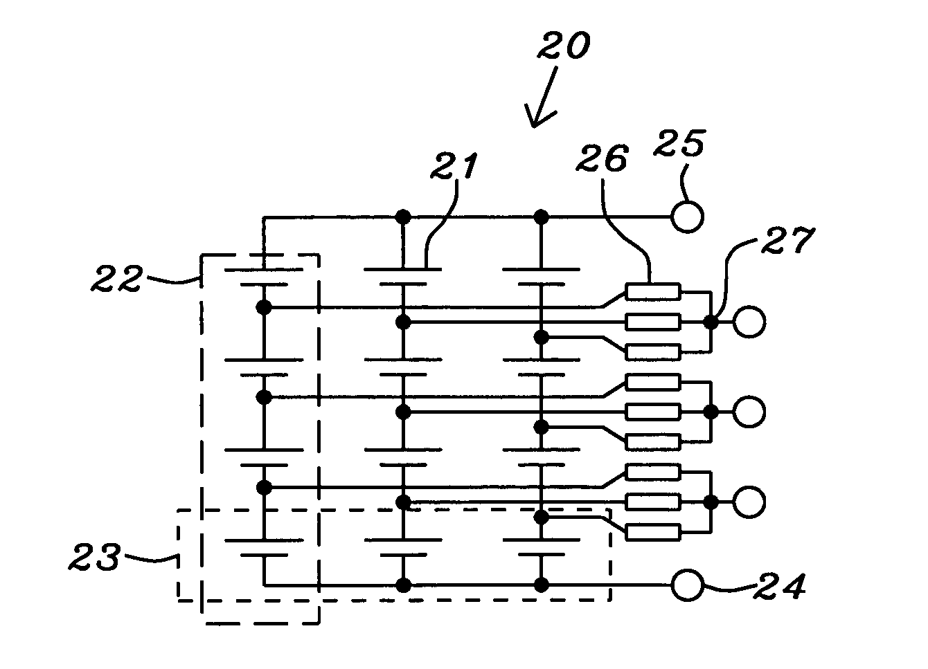
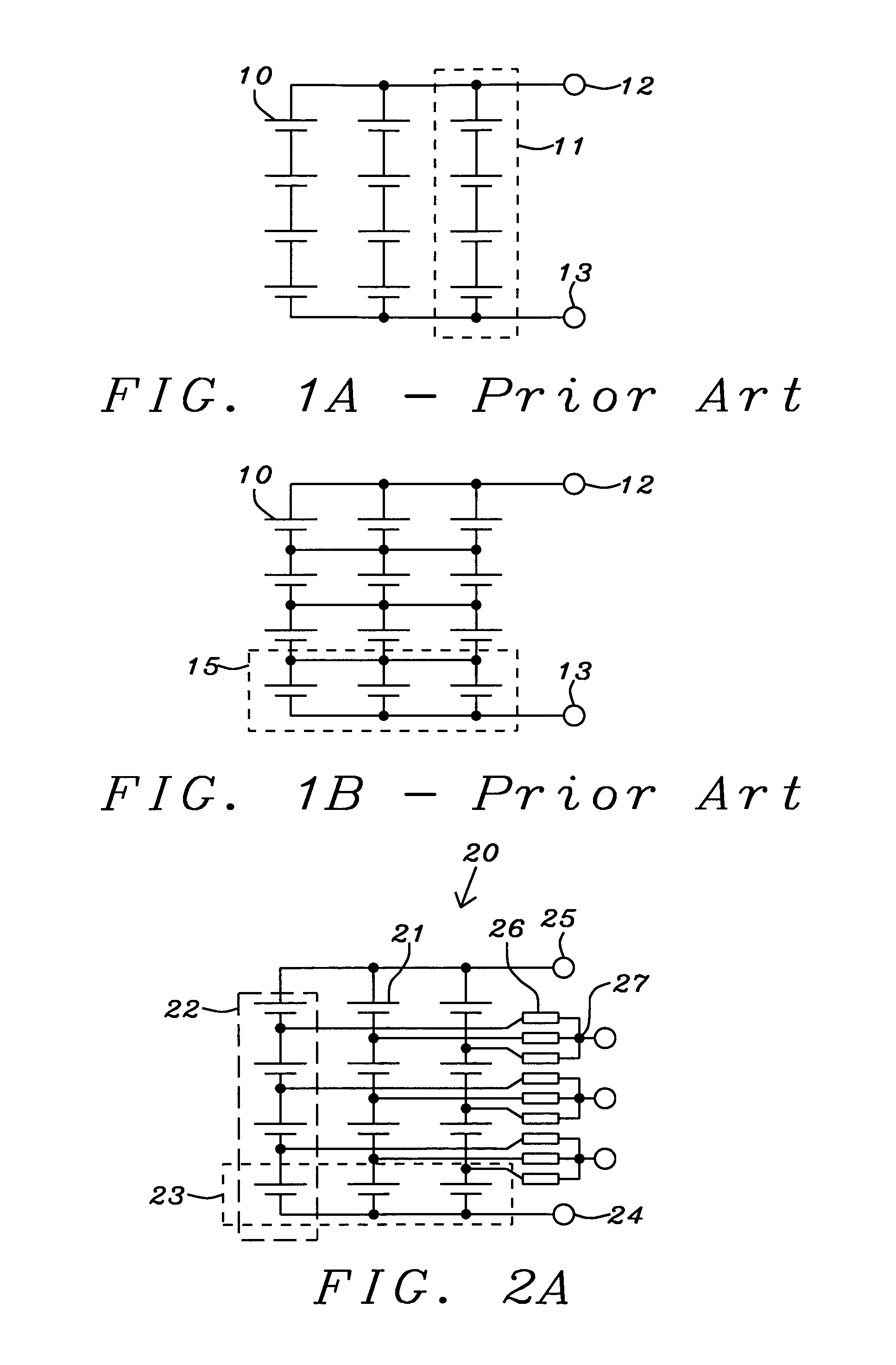
[0032]Shown in FIG. 2A is the present invention, which represents a symmetrical hard-series, soft-parallel arrangement 20 of batteries, or battery cells 21. The batteries 21 are connected in a column of series connected batteries 22 between the minus 24 and positive 25 terminals of the battery system, and then a number of these columns of series connected batteries are connected in parallel forming rows 23 of batteries across the columns. It should be noted that although FIG. 2 shows three columns 22 of four serial connected batteries 21, a more general configuration is m columns of n serial connected batteries that is within the scope of the present invention.

[0033]Connected to each positive terminal of each battery 21 is a resistor 26, except at the positive end of each series, which connects to the positive terminal 25 of the battery system. The resistors 26 of each row of batteries 23 are further connected to a measurement node 27. In FIG. 2 where n=4 there are n−1=3 measurement...

second embodiment

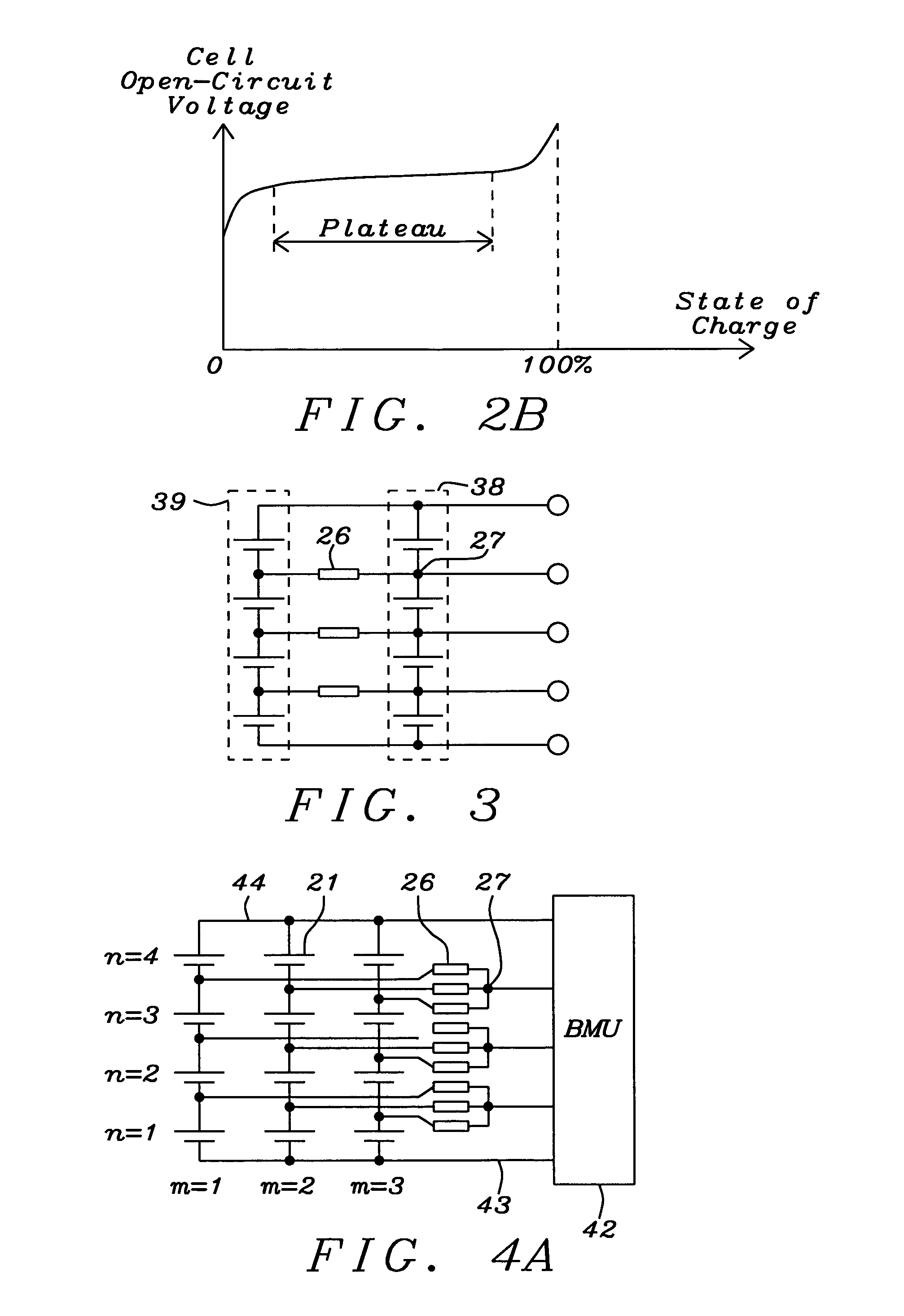
[0043]In FIG. 4B is shown an example of the present invention coupled to a BMU, where the second column (m=2) is shown to be the primarily series. However the physical location of primary series is arbitrary. In both FIG. 4A and FIG. 4B, a hard-series, soft-parallel arrangement of batteries 21, or battery cells, is shown with n=4 batteries hard-connected in series, and m=3 columns soft-connected in parallel.

[0044]BMU pins and connections unaffected by this invention, for example connection to the temperature sensor(s), to the current sensor, and to the charge / discharge switches, are omitted for clarity. It should be noted that the BMU connection in both FIG. 4A and FIG. 4B are identical to that of a conventional parallel-series configuration. In the first embodiment, the voltage monitor and balancing algorithm, including parameter setting, can be identical to that of a conventional parallel-series configuration. In the second embodiment, the voltage balancing algorithm and parameter...


PUM

PropertyMeasurementUnit
internal resistanceaaaaaaaaaa
resistanceaaaaaaaaaa

Abstract

A series-parallel battery system with a buffer resistor coupled to each junction of batteries or battery cells. Buffer resistors on the same row are coupled to a measurement node. Terminals of the battery system and the measurement nodes are treated as measurement points that are coupled to a conventional battery management unit. The buffer resistors provide a means for limiting in-rush current and a means for maintaining voltage balance across the row of batteries in the parallel columns of batteries. A control unit in series with each series of batteries monitors current in the series and comprises a switch to deactivate the column when the current exceeds a set of predetermined current levels.

Description

BACKGROUND OF THE INVENTION[0001]1. Field of Invention[0002]This invention relates to batteries, in particular to large capacity secondary batteries comprising multiple cells.[0003]2. Description of Related Art[0004]A secondary battery is a rechargeable battery, whereas a primary battery is a battery that cannot be recharged. A lithium-ion secondary battery exhibits high voltage, high capacity, and low self-discharge, and is popular source of portable electrical energy. However compared with other types of secondary batteries, a lithium-ion battery poses greater safety hazard. Therefore constant monitoring and control of its current, voltage, temperature, and some other parameters under a battery management unit (BMU) are often required.[0005]A cell is a basic electrochemical unit capable of storing electrical energy, but not necessarily resilient against handling and environmental stresses. A battery comprises at least one cell, and is physically resilient enough to survive reasona...

Claims


Application Information

Patent Timeline
Patent Type & Authority Patents(United States)
IPC IPC(8): H01M10/44H01M10/0525H01M10/48
CPCH01M10/482H01M10/0525H01M10/617Y02E60/10H02J7/0018H02J7/0047
Inventor ZHU, LI-YAN
Owner AMPEREX TECH
Learn More