
Distributed thermoelectric string and insulating panel

a technology of distributed thermoelectric string and insulating panel, which is applied in the manufacture/treatment of thermoelectric devices, lighting and heating apparatus, and the operation mode of machines, etc. it can solve the problems of reducing the overall performance, and requiring expensive materials for vacuum cavities. , to achieve the effect of dissipating thermal energy, reducing overall energy consumption, and dissipating heating and cooling

Active Publication Date: 2015-03-03
LEAR CORP
View PDF85 Cites 20 Cited by
  • Summary
  • Abstract
  • Description
  • Claims
  • Application Information

AI Technical Summary

Benefits of technology

[0015]Broadly speaking, this invention makes possible thermoelectric capability for a variety of panel materials and enables local / personal heating and cooling that reduces overall energy consumption. In one aspect this invention provides a thermoelectric string that can be woven or inserted into a variety of such panels, including soft and low-temperature panels. In another aspect, this invention also eliminates the need for a large, bulky, heavy, and expensive heat sinks and fans to dissipate heating and cooling. In one aspect this invention combines hardware that moves electrical current with hardware that dissipates thermal energy, thereby saving cost over embodiments such as U.S. Pat. No. 3,196,524. In another aspect this invention provides a common set of hardware to provide low thermal back flow near the thermoelectric elements and simultaneously provide high thermal conduction to ambient air away from the elements. In one embodiment this invention provides a thermoelectric string that can be routed through small holes in the panel to minimize thermal leakage. In another embodiment this invention eliminates the need for vacuum enclosures such as U.S. Pat. No. 3,225,549 of highly-distributed thermoelectric elements and also eliminate the need for wicking fluids such as US 2010 / 0107657. In a particularly preferred embodiment this invention provides cooling capability and electricity generation for pennies per watt in manufacturing cost.

Problems solved by technology

When these modules are deployed, large and heavy heat sinks and powerful fans are required to dissipate or absorb the heat on each side.
To achieve a low density packing of thermoelectric elements, one could space out these elements on the boards laterally, but then the backflow of heat conducted and radiated through the air between the elements limits the overall performance.
Some designs require evacuating the module interior to reduce heat backflow due to air conduction, but vacuum cavities require expensive materials and are prone to leaks.
Vacuum materials (like glass and Kovar™) are also hard and easily broken when thin enough to limit their own backflow of heat.
Broken glass can lead to safety issues when these modules are used in seat cushions, automobiles, and other environments.
Another problem in spreading out thermoelectric elements is that the rigid connection of elements over large distances causes them to rupture due to sheer stress upon thermal expansion of the hot side relative to the cold side.
To solve this problem, other designs have been proposed that use a flexible plastic such as polyimide for the circuit boards, but these materials are too porous to maintain a vacuum.
Another disadvantage of the prior art design of thermoelectric modules is that the high density of heat moved to the hot side results in a temperature gradient through the heat sink, and this temperature delta subtracts from the overall cooling that the module can achieve.
In particular, traditional thermoelectric products are not able to reach true refrigeration temperature because of this temperature gradient.
Unfortunately, many desired uses of cooling and heating involve close or direct contact with the human body, for which soft materials, such as cushions, cloths, and flexible foam are preferred, but these materials cannot withstand the high temperatures of a solder reflow oven.
The total energy savings of the central A / C or heating system plus the local thermoelectric systems can be 30% or more for such a combination, but the unwieldy implementation of prior-art thermoelectric modules inhibits their use for this purpose.
Devices that generate electricity from renewable sources all have limitations.
Photovoltaic (PV) technology has the following limitations: (1) high cost, (2) generates power only when the sun is shining brightly which is less than 33% of the time, (3) introduces transients into the electrical grid when clouds suddenly block the sun, and (4) low efficiency without concentration or dangerous temperatures and light levels with concentration.
Wind turbines have the following limitations: (1) relatively high cost, (2) generates power only when the wind is blowing which is less than 33% of the time on average, (3) introduces transients into the electrical grid when the wind suddenly stops or changes direction, (4) requires very tall and visually unacceptable structures, (5) generates noise, (6) has a random peak capacity time during the day that rarely matches the peak demand time, and (7) has very low land usage at about 4 Kwatts per acre.
Both PV and wind turbines may be supplemented with large batteries to store energy for periods of time when the renewable source is not available, but such storage is very expensive at about $1000 per Kwatt hour.
Tidal and wave energy installations require high capital startup costs, and like wind turbines, suffer from variable output and may be usually unacceptable structures if erected near shorelines.

Method used


Image

  • Distributed thermoelectric string and insulating panel
  • Distributed thermoelectric string and insulating panel
  • Distributed thermoelectric string and insulating panel

Examples


example 1

A Thermoelectric Cooler using Invention

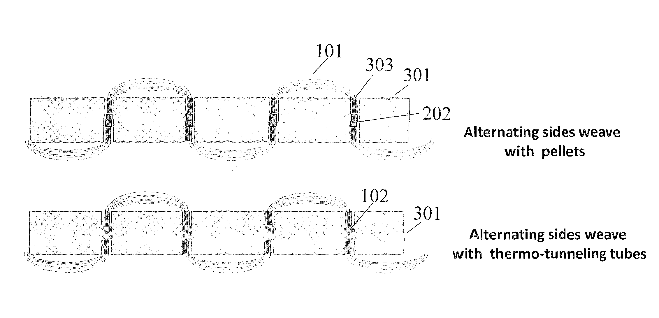
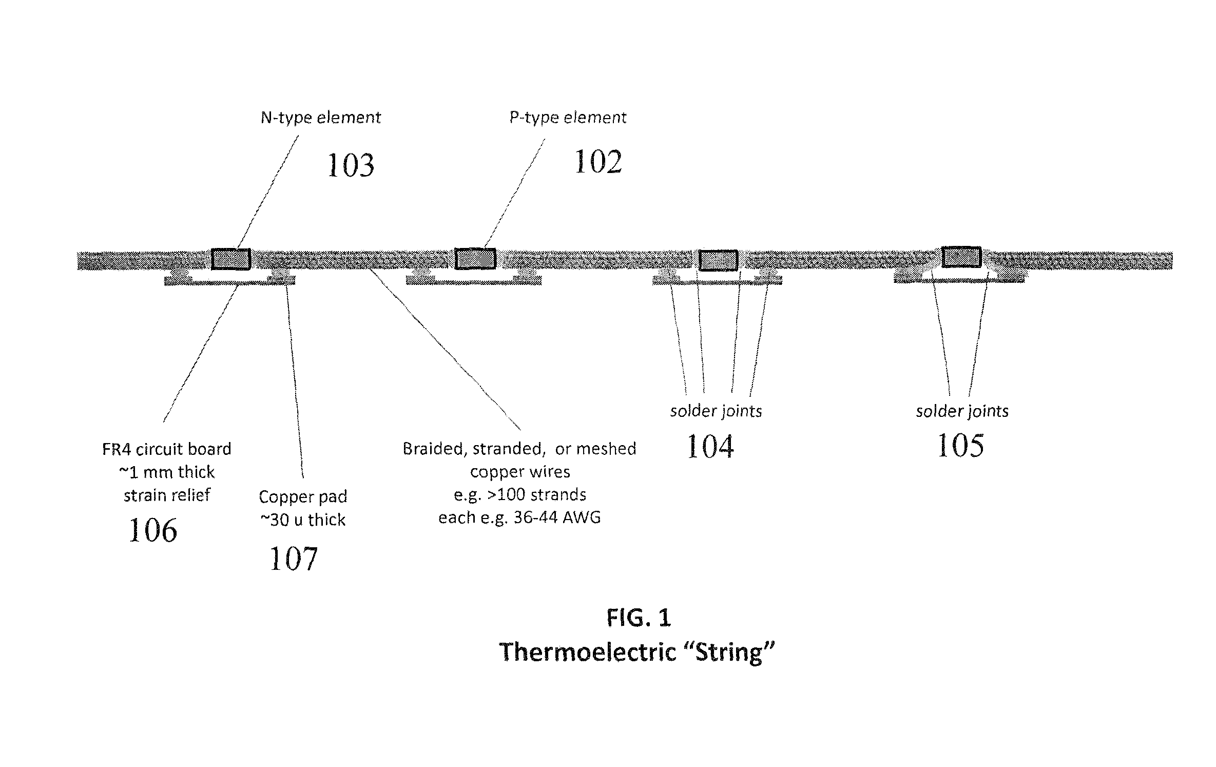
[0044]FIG. 7a illustrates a thermoelectric cooler 701 using the invention. Four thermoelectric panels 505 were built using a string as shown in FIG. 1 with braid 101 lengths 7 and 11 cm for the cold and hot sides, respectively. The panels were 1-inch (2.54 cm) thick Styrofoam™ 301 with 3 mm diameter holes and a pellet spacing of 3 cm. A total of 256 pellets were inserted into the four populated panels. The four thermoelectric panels were combined with two plain Styrofoam™ panels to construct a small cooler. The invention cooler 701 in FIG. 7a did not contain a heat sink or a fan and was powered with 20 watts of electricity.

[0045]The invention prototype of FIG. 7a was compared with a prior art commercial cooler 702 that contains a prior art thermoelectric module 704 also with 256 pellets, a prior art heat sink 706, and a prior art fan 705. This commercial cooler was powered as designed with 40 watts of electricity.

[0046]FIG. 7d shows the data ta...

example 2

Solar Power Storage and Electricity Generation

[0060]An example power generator in accordance with FIG. 9 will now be described that is competitive with other power generators such as wind turbines and photovoltaic panels. The heat storage medium 905 is 2 m×2 m×0.3 m and is assumed to reach a peak of 100° C. This temperature does not exceed the boiling point of water, and is a temperature easily reached by insulated solar ovens used to cook food. The cold side 901 temperature is assumed to be room temperature or 20° C. The delta temperature ΔT across the thermoelectric panel 902 is then 80° C. and the average temperature is 60° C. The heat storage medium at a temperature elevated by 80° C. relative to ambient stores 4.0 E+8 joules or 112 Kwatt-hours if the heat capacity of water at 4.2 joules / cm3° C. is assumed.

[0061]The insulating material 903 dimensions are 2 m×2 m×0.05 m, and so the thermal loss through the thickness of the insulator at the ΔT of 80° C. is 147 watts if a typical t...


PUM

PropertyMeasurementUnit
thicknessaaaaaaaaaa
thickaaaaaaaaaa
perimeteraaaaaaaaaa

Abstract

Inexpensive, lightweight, flexible heating and cooling panels with highly distributed thermoelectric elements are provided. A thermoelectric “string” is described that may be woven or assembled into a variety of insulating panels such as seat cushions, mattresses, pillows, blankets, ceiling tiles, office partitions, under-desk panels, electronic enclosures, building walls, refrigerator walls, and heat conversion panels. The string contains spaced thermoelectric elements which are thermally and electrically connected to lengths of braided, meshed, stranded, foamed, or otherwise expandable and compressible conductor. The elements and a portion of compacted conductor are mounted within the insulating panel On the outsides of the panel, the conductor is expanded to provide a very large surface area of contact with air or other medium for heat absorption on the cold side and for heat dissipation on the hot side.

Description

CROSS REFERENCE TO RELATED APPLICATIONS[0001]This application claims priority from U.S. Provisional Application Ser. No. 61 / 403,217, filed Sep. 13, 2010; U.S. Provisional Application Ser. No. 61 / 417,380, filed Nov. 26, 2010, U.S. Provisional Application Ser. No. 61 / 433,489, filed Jan. 17, 2011, and from U.S. Provisional Application Ser. No, 61 / 470,039 filed Mar. 31, 2011, the contents of which are incorporated herein by reference.BACKGROUNDCooling and Heating[0002]Thermoelectric modules typically contain densely packed elements spaced apart by 1-3 mm. Up to 256 such elements are connected in an array that is 2×2 inches (5.08×5.08 cm) in area. When these modules are deployed, large and heavy heat sinks and powerful fans are required to dissipate or absorb the heat on each side. The reasons for these dense prior art configurations are well-founded: small elements with low resistance allow larger current I to flow before the resistive heat (I2R) generated destroys the thermoelectric co...

Claims


Application Information

Patent Timeline
Patent Type & Authority Patents(United States)
IPC IPC(8): H01L35/04H01L35/28H01C17/00H01L35/34H01C1/16H01C7/00H01L35/32
CPCH01C7/008H01L35/32H01C1/16Y10T29/49082H10N19/101H10N10/01H10N10/17F25B21/04
Inventor MAKANSI, TAREKWOODFRANKLIN, JOHN L.EVERS, MARK N.
Owner LEAR CORP
Learn More