
Conductive sheet and production method for same

a technology of conductive sheets and production methods, which is applied in the field of conductive sheets, can solve the problems of low conductivity of polyarylate non-woven fabric or glass fiber non-woven fabric used as a base material, low production efficiency of fuel cells using water-repellent conductive sheets as electrode materials, and high cost of fuel cells, so as to prevent the dry out of the electrolyte membrane, improve the conductivity, and improve the effect of water-exhausting properties

Active Publication Date: 2014-12-23
TOHO TAYON CO LTD
View PDF28 Cites 4 Cited by
  • Summary
  • Abstract
  • Description
  • Claims
  • Application Information

AI Technical Summary

Benefits of technology

The present invention provides a conductive sheet that can be used as an electrode material for fuel cell. The sheet has conductivity, gas diffusibility, and hydrophobicity which makes it suitable for water management in fuel cells. The sheet can be easily produced and has high productivity. The conductive sheet of the second embodiment allows for appropriate water control of the MEA and prevents electrolyte membrane dry-out under low-temperature humidity conditions. The conductive sheet of the third embodiment has different injection pressures of water on the two surfaces which prevents reaction water from penetrating into the GDL. Overall, the conductive sheet of the present invention is suitable for various fuel cells, particularly polymer electrolyte fuel cells.

Problems solved by technology

However, the water-repellent conductive sheet is produced via many steps as described previously and therefore is low in production efficiency.
As a result, a fuel cell using the water-repellent conductive sheet as an electrode material is expensive.
However, in these methods, the conductivity of the polyarylate non-woven fabric or glass fiber non-woven fabric used as a base material is low and, therefore, a fuel cell using the electrode material has a high internal resistance.
As a result, no high cell performance is obtained.
However, since the noble metal used for coating is expensive, the fuel cell obtained is expensive.
However, production of an electrode material of high conductivity makes it necessary to impregnate the inside of base sheet with sufficient amounts of carbon fiber and carbon fine particles.
However, this method repeats coating of resin solution and drying and therefore is low in production efficiency.
Accordingly, a fuel cell using this sheet is low in cell performance.
This water-repellent conductive sheet is too high in the hydrophobicity of whole sheet.
As a result, the polymer membrane is dried especially under low-temperature humidity conditions, resulting in reduced cell performance (this phenomenon may be hereinafter referred as “dry-out”).
When lower hydrophobicity is employed in order to suppress the dry-out, flooding appears, resulting in reduced cell performance.
However, this method employs complicated steps similarly to the above-mentioned Patent Literature 3 and is low in production efficiency.
Also, the knot between layers invites a higher contact resistance and accordingly low cell performance.
Further, water stays easily between layers, tending to cause a reduction in performance by flooding.
However, containing no binder therein, the sheet has a low strength and is inferior in handling-ability, making difficult the assembling of cell.
Accordingly, part of the carbon fiber and water-repellent resin powder (both are components of the second layer) is impregnated into the first layer, giving rise to large spots, resulting in low cell performance.
Furthermore, it is impossible to produce a thin sheet.

Method used

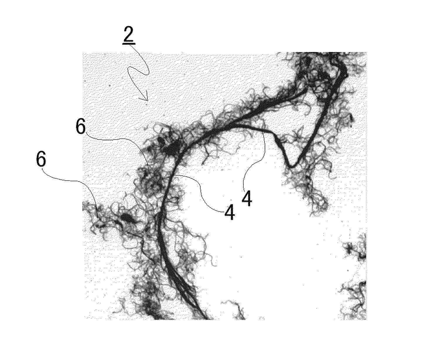
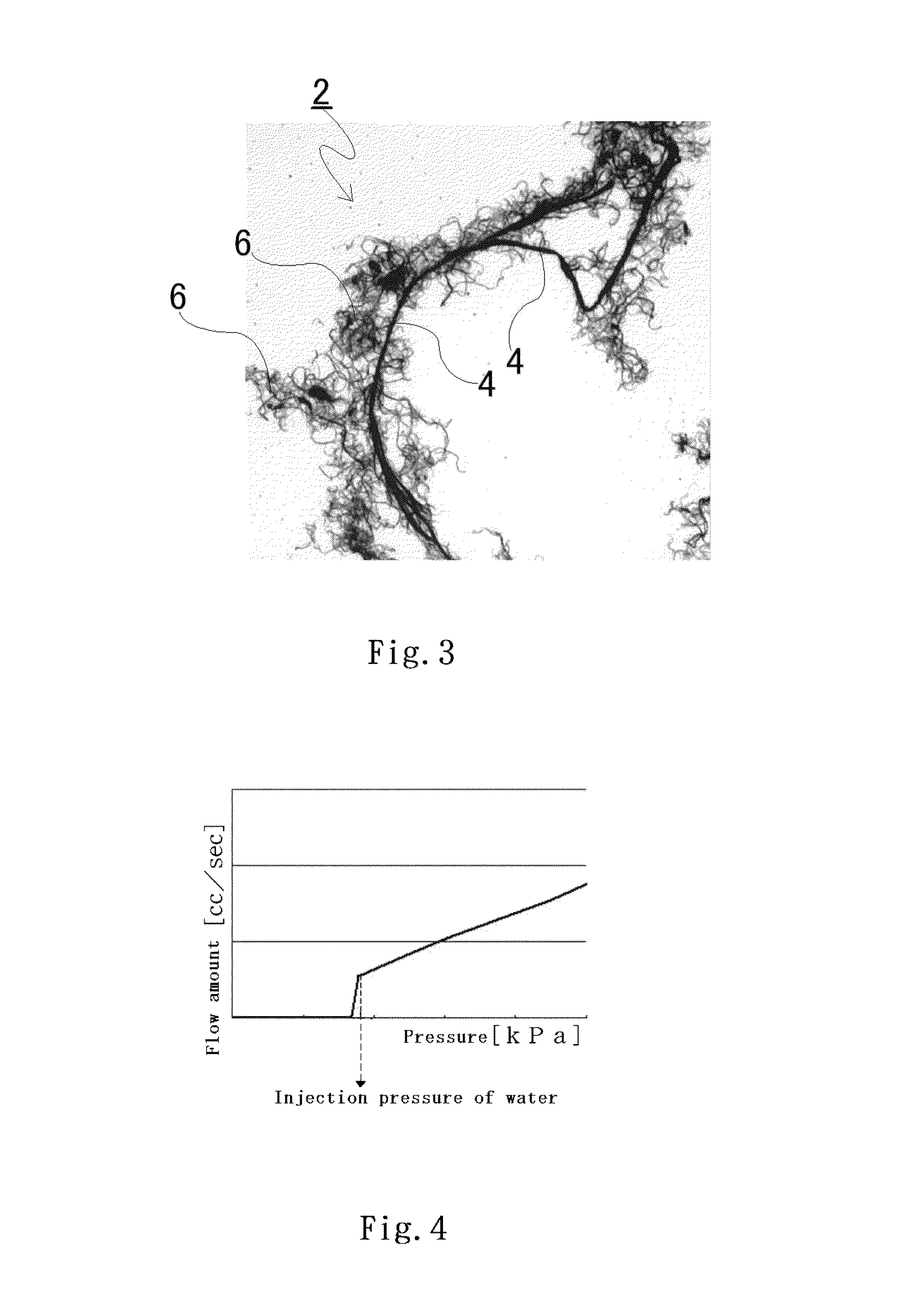

Image

  • Conductive sheet and production method for same
  • Conductive sheet and production method for same
  • Conductive sheet and production method for same

Examples


first embodiment

[0097]The first embodiment of the present invention is explained below.

(Conductive Sheet)

[0098]The conductive sheet of the first embodiment of the present invention (hereinafter, this sheet may be referred as “present conductive sheet”) is constituted by comprising an aromatic polyamide pulp, a fluoroplastic and a carbon-based conductive material. The fluoroplastic is fused to the fiber surface of the aromatic polyamide pulp. The fluoroplastic allows the present conductive sheet to have hydrophobicity. The carbon-based conductive material is dispersed between the fibers of the aromatic polyamide pulp. The carbon-based conductive material allows the present conductive sheet to have conductivity in the thickness direction of the sheet.

[0099]The thickness of the present conductive sheet is preferably 50 to 500 μm, particularly preferably 100 to 400 μm. With a thickness of smaller than 50 μm, the sheet has a low strength, making difficult the handling of the sheet. With a thickness of l...

second embodiment

[0158]The second embodiment of the present invention is explained below.

(Conductive Sheet)

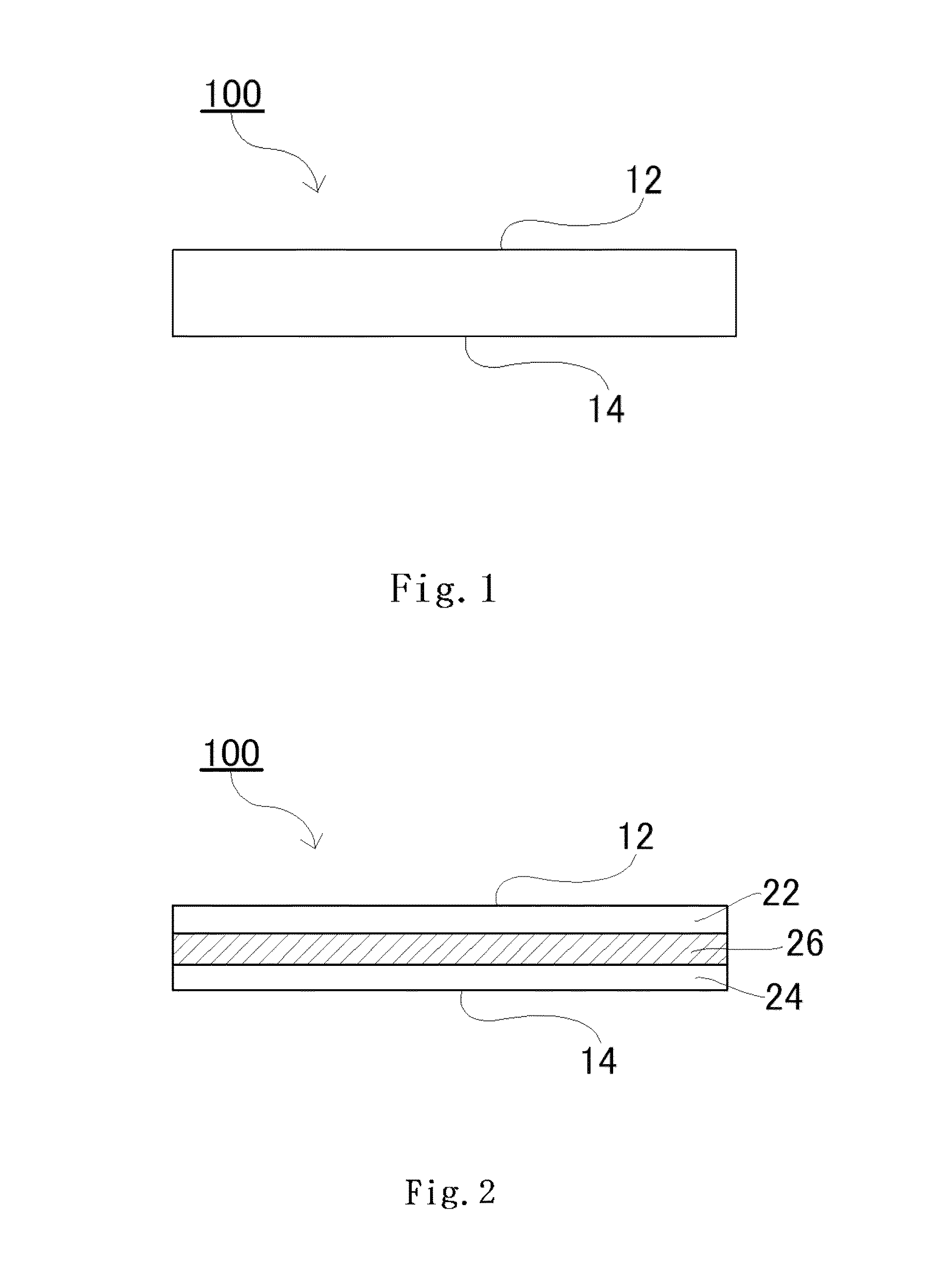
[0159]FIG. 1 is a side view showing an example of the conductive sheet of the second embodiment of the present invention.

[0160]The conductive sheet 100 of the present embodiment is constituted by comprising an aromatic polyamide pulp, a fluoroplastic and a carbon-based conductive material. The carbon-based conductive material is dispersed between the fibers of the aromatic polyamide pulp. This carbon-based conductive material allows the conductive sheet 100 to have conductivity in the thickness direction. The fluoroplastic is fused to the fiber surfaces of the aromatic polyamide pulp. This fluoroplastic allows the conductive sheet 100 to have hydrophobicity.

[0161]The amount of the fluoroplastic present on the surface of the conductive sheet 100 is different between the first surface 12 (one surface) of the conductive sheet 100 and the second surface 14 (opposite to the first surface 12) of the ...

third embodiment

[0190]The third embodiment of the present invention is explained below.

(Conductive Sheet)

[0191]The conductive sheet in the third embodiment of the present invention is explained using FIG. 1.

[0192]The conductive sheet 100 of the present embodiment comprises an aromatic polyamide pulp, a fluoroplastic and a carbon-based conductive material. The carbon-based conductive material is dispersed between the fibers of the aromatic polyamide pulp and allows the conductive sheet 100 to have conductivity in the thickness direction of the sheet. The fluoroplastic is fused to the fibers of the aromatic polyamide pulp and allows the conductive sheet 100 to have hydrophobicity. The contents of the aromatic polyamide pulp, the fluoroplastic and the carbon-based conductive material are each different between the first surface 12 (one surface) of the conductive sheet 100 and the second surface 14 (other surface opposite to the first surface 12). Accordingly, water infiltrability differs between the f...


PUM

PropertyMeasurementUnit
pore diameteraaaaaaaaaa
densityaaaaaaaaaa
static contact angleaaaaaaaaaa

Abstract

A conductive sheet comprises an aromatic polyamide pulp, a fluoroplastic fused to the aromatic polyamide pulp, and a carbon-based conductive material; wherein the conductive sheet has a static contact angle of water on a first surface that is greater than the static contact angle of water on a second surface that in the opposite surface to the first surface, and the difference between the static contact angle of water on the first surface and the static contact angle of water on the second surface is 20°-180°; or wherein the injection pressure of water on the first surface of the conductive sheet is less than the injection pressure of water on the second surface that is the opposite surface to the first surface, and the difference between the injection pressure of water on the first surface and the injection pressure of water on the second surface is 20-50 kPa.

Description

[0001]This application is a 371 application of PCT / JP2011 / 069074 filed Aug. 24, 2011, which claims foreign priority benefit under 35 U.S.C. §119 of Japanese application Nos. 2010-191353 filed Aug. 27, 2010, 2011-083237 filed Apr. 5, 2011 and 2011176966 filed Aug. 12, 2011.TECHNICAL FIELD[0002]The present invention relates to a conductive sheet and a method for producing the conductive sheet. More particularly, the present invention relates to a conductive sheet comprising a fluoroplastic and a conductive material, as well as to a method for producing the conductive sheet. The conductive sheet of the present invention is useful as an electrode material, particularly as an electrode material for fuel cell.BACKGROUND ART[0003]Fuel cell is divided into four kinds depending upon the kind of the electrolyte used therein, i.e. molten carbonate fuel cell (MCFC), solid oxide fuel cell (SOFC), phosphoric acid fuel cell (PAFC) and polymer electrolyte fuel cell (PEFC). Lately, development is un...

Claims


Application Information

Patent Timeline
Patent Type & Authority Patents(United States)
IPC IPC(8): H01B1/24H01M4/86H01M8/02H01M4/96
CPCH01M8/0234H01M8/0243H01B1/24H01M8/0245H01M4/8652Y02E60/50H01M8/0239H01M4/8605H01M4/86H01M4/8657H01M4/8673H01M4/8842H01M4/8896H01M4/96H01M8/02H01M8/10Y02P70/50
Inventor KUROKAWA, KAZUMAAKAMATSU, TETSUYA
Owner TOHO TAYON CO LTD
Learn More