
LED lamp control circuit

a technology for controlling circuits and led lamps, applied in process and machine control, electric variable regulation, instruments, etc., can solve problems such as inability to realize lighting functions, shortened service life of leds, and rejection of lamps, so as to ensure stable operation of the whole circuit, reduce shock, and prevent damage to constant current source devices

Inactive Publication Date: 2014-11-04
NANKER GUANGZHOU SEMICON MFG
View PDF8 Cites 2 Cited by
  • Summary
  • Abstract
  • Description
  • Claims
  • Application Information

AI Technical Summary

Benefits of technology

[0026]The present invention has advantageous effects as below. The circuit controlling the LED lamp comprises a rectifier circuit for changing an alternating current into a direct current, a LED light source load, a constant current circuit for regulating voltage and current for the LED light source load, and a first temperature control switch circuit, wherein the LED light source load comprises at least one group of plural LEDs connected in series; the constant current circuit comprises at least one group of constant current source devices with each group being connected in series to at least one group of the LEDs in the LED light source load and comprising at least one depletion mode field effect transistor, of which a drain serves as the contact and a source is short circuited with a grid to serve as the other contact; the first temperature control switch circuit is connected to the input of the power supply, and comprises a first normally closed temperature control switch; and the first normally closed temperature control switch is mounted on the heat sink or at the specific position in the lamp, and is disconnected when the temperature of the heat sink or the temperature at the specific position in the lamp exceeds the disconnection temperature of the first normally closed temperature control switch, which is a specific temperature between 60 and 100° C., to cut off the power supply of the LED light source load. On account of the above, the constant current source devices, as independent devices, conveniently replace peripheral voltage regulation and current regulation circuits of other circuits in the prior art, so that circuit components are greatly reduced, and the circuit is simple and low in cost. By means of providing the first temperature control switch circuit connected to the input of the power supply in a way that the normally closed temperature control switch is disconnected when the temperature of the heat sink or the temperature at the certain specific position in the lamp exceeds the disconnection temperature of the normally closed temperature control switch to cut off the power supply of the LED light source load, and is reclosed when the temperature of the heat sink is lower than the disconnection temperature of the normally closed temperature control switch to lighten the LEDs for lighting, short service lives and rejection of the LEDs due to overheat are avoided, the service lives of the LEDs are prolonged, and the LEDs are protected from being damaged by high temperature. Thus, the present invention is simple in structure and reliable in control, and has a high-temperature protection function.
[0027]Since each group of the constant current source devices is connected in parallel to the first Zener diode with the operating point being the specific voltage between 20 and 80V DC, provision of the first Zener diode that controls the voltage of the constant current source devices within a certain range avoids overly high instantaneous voltage caused by switching surge shock produced when a plurality of lamps are simultaneously turned on, reduces shock to the constant current source, prevents the constant current source devices from being damaged, and ensures stable operation of the whole circuit, so the present invention is simple in structure and reliable in control and has a key component overvoltage protection function.
[0028]The circuit controlling the LED lamp further comprises a second temperature control switch circuit comprising a second normally closed temperature control switch and a voltage dividing resistor connected in parallel to the second normally closed temperature control switch, and the second normally closed temperature control switch is mounted on the power board and is disconnected when the circuit ambient temperature exceeds the disconnection temperature of the second normally closed temperature control switch, which is a specific temperature between 30 and 100° C., so that the current passes through the voltage dividing resistor to reduce the power supply current of the LED light source load. On account of the above, when the working ambient temperature reaches the disconnection temperature of the second normally closed temperature control switch, the current passes through the voltage dividing resistor to reduce the power supply current of the LED light source load, so that the power of the LED light source is reduced, heat is reduced, and the lamp can still be kept in a lighting state at an extreme ambient temperature to meet the service requirement. The above solution keeps operating in a low-power state even at a rather high temperature to meet the service requirement, so the present invention can still light at a higher temperature.
[0029]Since the circuit controlling the LED lamp further comprises a cooling fan motor and a fan protection circuit connected in parallel to the cooling fan motor, which comprises at least one fan shunt resistor and a second Zener diode connected in parallel to the fan shunt resistor with an operating point being a specific voltage between 5 and 24V DC, provision of the second Zener diode that controls the voltage of the cooling fan motor within a certain range avoids overly high instantaneous voltage caused by switching surge shock produced when a plurality of lamps are simultaneously turned on, reduces shock to the cooling fan motor, prevents the cooling fan motor from being damaged, and ensures stable operation of heat dissipation of the whole circuit, so the present invention also has a fan overvoltage protection function;
[0030]The circuit controlling the LED lamp further comprises a third temperature control switch circuit connected in series to the lamp fan motor and then connected in parallel to the fan protection circuit, and the third temperature control switch circuit comprises a normally open temperature control switch that is closed when the temperature exceeds the close temperature of the normally open temperature control switch, which is a specific temperature between 30 and 50° C., to supply power to the lamp fan motor. On account of the above, the normally open temperature control switch is closed when the temperature exceeds the close temperature of the normally open temperature control switch to supply the power to the lamp fan motor so that the fan works and actively dissipates heat, and is disconnected when the temperature is lower than the close temperature of the normally open temperature control switch so that the lamp fan motor does not work to avoid waste and noise and further avoid disadvantages caused by forcibly starting an icing fan in special low-temperature occasions, so the present invention has a low-temperature protection function.

Problems solved by technology

If an LED works at a high temperature for a long term, the service life of the LED could be greatly shortened, the exertion of advantages of the LED could be affected, and even a dead lamp phenomenon could be caused eventually leading to rejection of the lamp.
But in some cases, even if the temperature is high, lighting is still needed, and at this moment, if the lamps are turned off, the lighting function cannot be realized, and the service requirement cannot be met.
In addition, in an environment where a plurality of LED lamps are simultaneously used, if the plurality of LED lamps are simultaneously turned on, a switching surge shock is produced, and the voltage instantaneously fluctuates within a large range.
Once the instantaneous voltage is overly high, key components in the circuit may be shocked.
Once the instantaneous voltage exceeds the bearing capacity of the components, the key components are damaged to cause death and rejection of the LED lamps.

Method used


Image

  • LED lamp control circuit
  • LED lamp control circuit
  • LED lamp control circuit

Examples


embodiment i

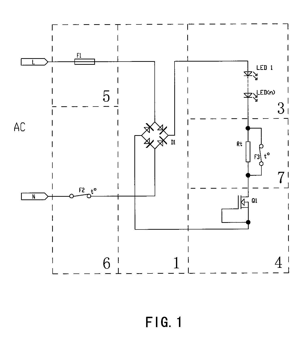
[0046]As shown in FIG. 1, FIG. 5, FIG. 6, FIG. 9 and FIG. 10, the LED lamp of this embodiment comprises a power board 101 for supplying power to an LED light source as well as a circuit controlling the LED lamp, a heat sink 102 for cooling the LED light source, a waterproof and dustproof lampshade 103 and a reflector 104, wherein the circuit controlling the LED lamp comprises a rectifier circuit 1 for changing an alternating current into a direct current, an LED light source load 3, a constant current circuit 4 that regulates voltage and current for the LED light source load 3, an overcurrent protection circuit 5, a first temperature control switch circuit 6 and a second temperature control switch circuit 7. The rectifier circuit 1 adopts bridge rectification with a rectifier bridge D1, and certainly can adopt other rectification modes for rectification. The overcurrent protection circuit 5 is connected to an input of a power supply with an overcurrent protection fuse F1 that fuses ...

embodiment ii

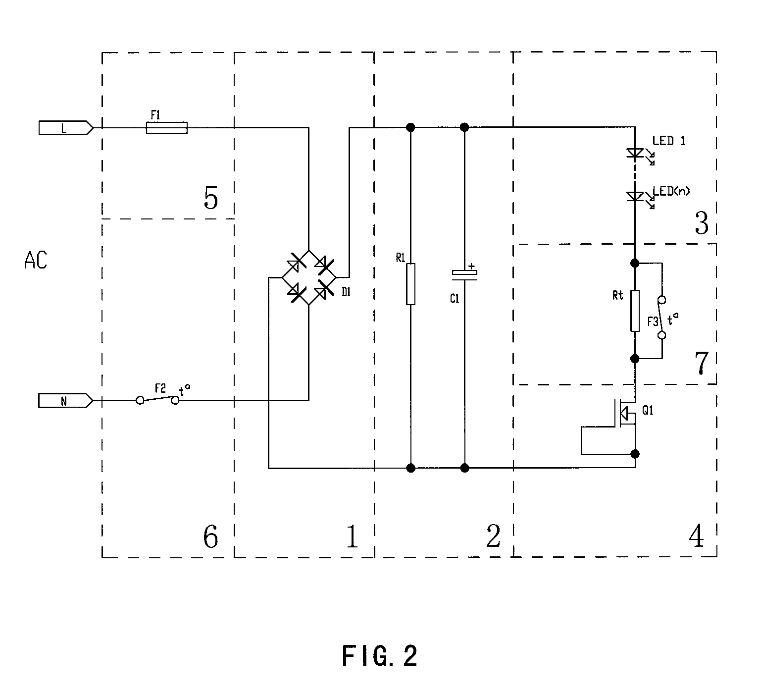
[0049]As shown in FIG. 2, FIG. 5, FIG. 6, FIG. 9 and FIG. 10, the difference between this embodiment and Embodiment I lies in: in this embodiment, the circuit controlling the LED lamp further comprises a filter circuit 2 connected behind the rectifier circuit 1 and comprising a filter capacitor C1 and a bleeder resistor R1, and can also adopt other filter circuits to supply a more stable current to the LED light source load 3. However, the power factor is affected to a certain extent due to addition of the filter capacitor.

[0050]The remaining features of this embodiment are the same as those of Embodiment I.

embodiment iii

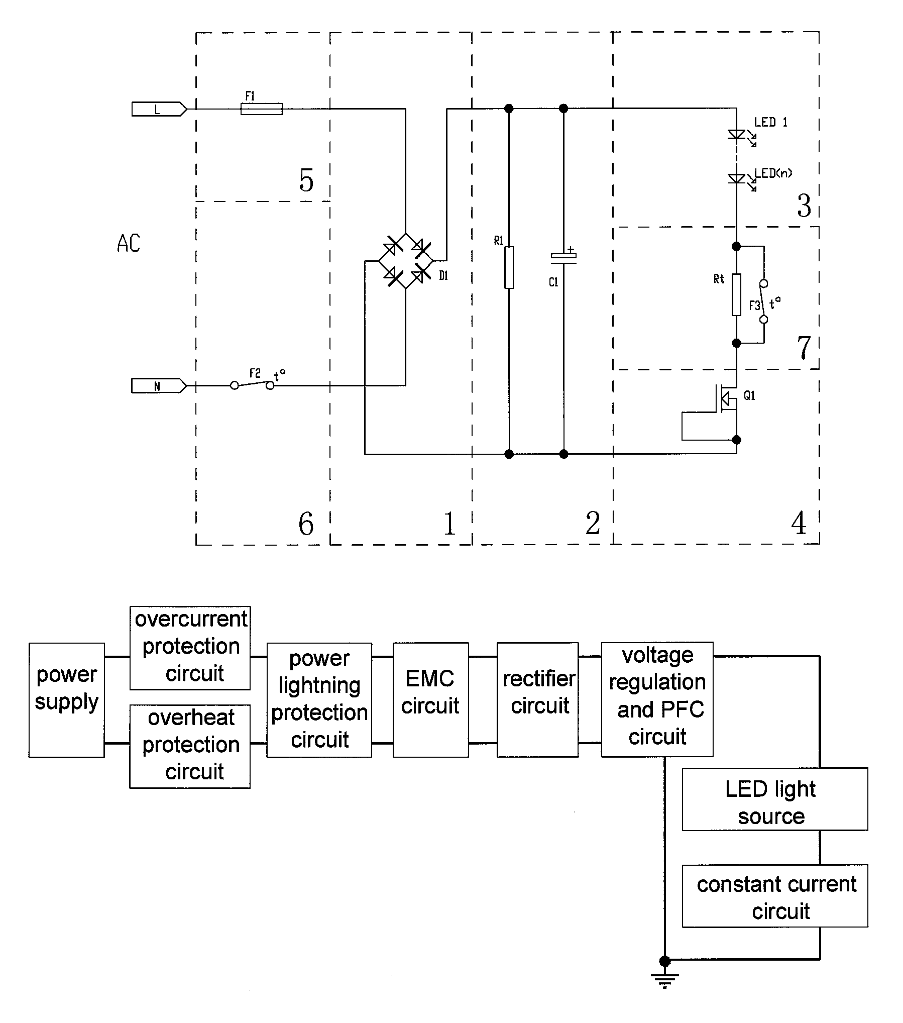
[0051]As shown in FIG. 3 and FIG. 7 to FIG. 10, the LED lamp of this embodiment comprises a power board 101 for supplying power to an LED light source as well as a circuit controlling the LED lamp, a heat sink 102 for cooling the LED light source, a waterproof and dustproof lampshade 103, a reflector 104, and a sealed power box 105 for proofing the power board 101 against water and dust, wherein the circuit controlling the LED lamp comprises a rectifier circuit 1 for changing an alternating current into a direct current, an LED light source load 3, a constant current circuit 4 that regulates voltage and current for the LED light source load 3, an overcurrent protection circuit 5, a first temperature control switch circuit 6, a second temperature control switch circuit 7, a power lightning protection circuit 8, a power supply EMC circuit 9, a voltage regulation and PFC circuit 10, and a light source EMC circuit 11; the rectifier circuit 1 adopts bridge rectification with a rectifier ...


PUM


Abstract

An LED lamp control circuit comprises a rectifier circuit, an LED light source load, a constant current circuit, and a first temperature detect switch circuit. The LED light source load comprises at least one group of LEDs. The constant current circuit comprises at least one group of constant current source components, each of which is connected to at least one group of LEDs in the LED light source load and comprises a depletion mode field effect transistor. The first temperature detect switch circuit is connected to an input end of a power source, and comprises a first normally closed temperature detect switch mounted on a radiator. When the temperature of the radiator exceeds the disconnection temperature of the first normally closed temperature detect switch, the first normally closed temperature detect switch is disconnected, so as to cut off the power supply of the LED light source load.

Description

CROSS-REFERENCE TO RELATED PATENT APPLICATIONS[0001]This application is a U.S. National Phase Application under 35 U.S.C. §371 of International Patent Application No. PCT / CN2012 / 075210, filed May 8, 2012, and claims the benefit of Chinese Patent Applications No. 201110129786.3, filed on May 17, 2011 and No. 201110270659.5, filed Sep. 14, 2011, all of which are incorporated by reference in their entirety herein. The International Application was published on Nov. 22, 2012 as International Publication No. WO / 2012 / 155801 under PCT Article 21(2).FIELD OF THE INVENTION[0002]The present invention relates to an LED lamp control circuit.BACKGROUND OF THE INVENTION[0003]At present, LEDs are applied more and more widely, and LED lamps for daily indoor and outdoor lighting are more and more popular. The present LED lighting is increasingly developed towards the high power direction, and the high heat brought by high-power LEDs is an important factor puzzling the popularization of the LEDs. If ...

Claims


Application Information

Patent Timeline
Patent Type & Authority Patents(United States)
IPC IPC(8): H05B33/08H05B33/02H05B44/00
CPCH05B33/0827H05B33/0815H05B33/0812Y02B20/345Y02B20/347H05B33/0884H05B45/395H05B45/46Y02B20/30H05B45/3725H05B45/56H05B45/54
Inventor WU, CHUN-WEI
Owner NANKER GUANGZHOU SEMICON MFG
Learn More