Eureka AIR delivers breakthrough ideas for toughest innovation challenges, trusted by R&D personnel around the world.

Compact coherent high brightness light source for the mid-IR and far IR

a high-brightness, coherent technology, applied in the direction of instruments, cladded optical fibres, optical elements, etc., can solve the problems of limited optical conversion efficiency, performance constraints, limited output power of mid-ir to far-ir light sources, etc., to maximize the temporal overlap between the low frequency and high frequency spectral components inside the dfg crystal, optimize the temporal overlap, and increase the output power

Active Publication Date: 2014-10-14
IMRA AMERICA
View PDF39 Cites 17 Cited by
  • Summary
  • Abstract
  • Description
  • Claims
  • Application Information

AI Technical Summary

Benefits of technology

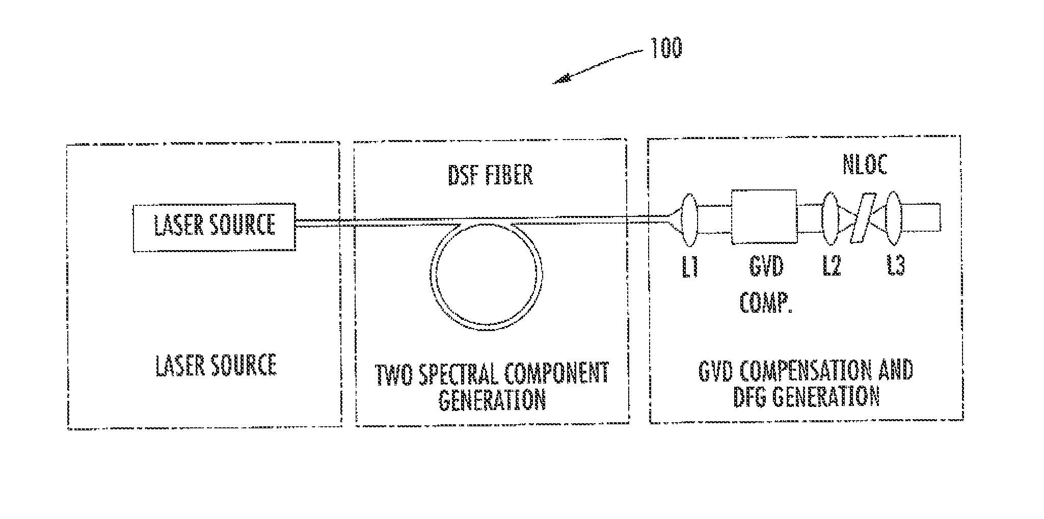
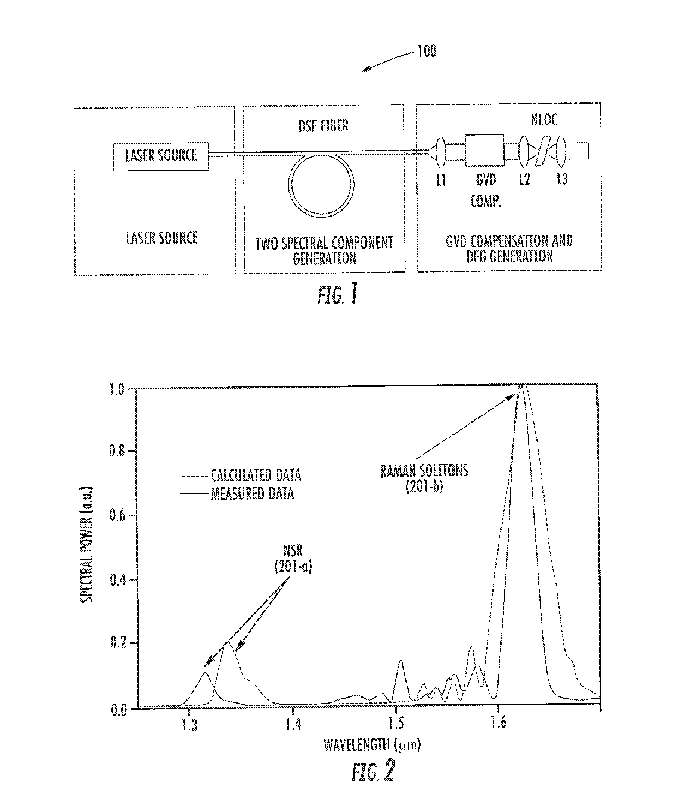
[0010]To increase the spectral bandwidth of the sources, at least a fraction of the output of the high power pump sources are coupled into a highly nonlinear fiber or waveguide designed with a zero dispersion wavelength near the output wavelength of the source, thereby generating a spectrally broadened source.
[0011]As disclosed in ‘Broadband Generation of Coherent Continua with Optical Fibers’, U.S. Patent Application No. 61 / 483,472, ('472), filed May 6, 2011, to Fermann et al., the coherence of spectrally broadened sources is increased by implementing highly nonlinear fibers or waveguides that produce a supercontinuum output characterizable by a first order coherence function having a value>0.9 at two spectral locations within said supercontinuum, wherein said spectral locations are separated by at least half an octave. Alternatively, a high level of coherence of the spectrally broadened source is ensured by using nonlinear fibers with high levels of Germania concentrations or nonlinear fibers or waveguides with a relatively high vibrational contribution to their nonlinear response function.
[0012]Frequency conversion of the ultrafast laser sources to the mid-IR and far-IR is facilitated via coupling the spectrally broadened output into a nonlinear crystal designed for DFG. Difference frequencies are generated between the high power pump source frequency component(s) and frequency components(s) of the spectrally broadened source while ensuring temporal overlap of pulses generated by the two sources via appropriate optical delay stages.
[0013]Alternatively, frequency conversion of the ultrafast laser sources to the mid-IR and far-IR is facilitated via coupling the spectrally broadened output into a nonlinear crystal designed for DFG between low and high frequency spectral components of the spectrally broadened output. More particularly, a frequency difference signal is generated with red and blue distal portions of the spectrally broadened output.
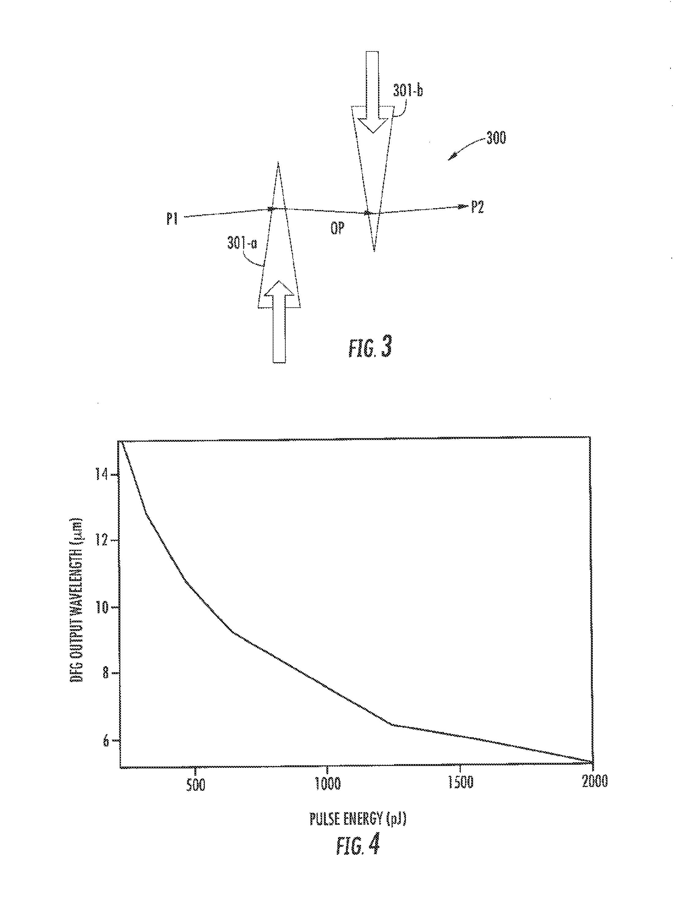
[0016]Preferably, temporal overlap between the low frequency and high frequency spectral components inside the DFG crystal will be maximized. In at least one embodiment optical elements with differential group delay between the low and high spectral components can be inserted upstream of the nonlinear DFG crystal. Also an appropriate combination of mirrors and beamsplitters can be implemented to optimize the temporal overlap between the low and high frequency spectral components.
[0017]To increase the output power of spectrally broadened sources, large core dispersion shifted fibers can be implemented. Such fibers can be based on highly germania doped fibers or soft-glass fibers.

Problems solved by technology

Prior art mid-IR to far-IR light sources are limited in output power, spectral coverage for wavelengths>5 μm, wavelength tunability, and / or limited optical conversion efficiency to the mid-IR.
Performance constraints can arise as a result of the limited coherence of the DFG pump sources and / or relatively complex system assembly involving typically two separate optical paths, a path delay adjustment stage, as well as a beam-splitter.
The main drawbacks of the prior art systems were, for example, limited coherence of the DFG output (Winters and Neely) or the lack of frequency down-conversion (Krauss).
In addition these systems were relatively large and incorporated many bulk optical components.

Method used


Image

  • Compact coherent high brightness light source for the mid-IR and far IR
  • Compact coherent high brightness light source for the mid-IR and far IR
  • Compact coherent high brightness light source for the mid-IR and far IR

Examples


Embodiment Construction

[0029]Mid-IR frequency generation has been discussed in U.S. Pat. No. 8,040,929 ('929) to Imeshev et al. entitled “Optical parametric amplification, optical parametric generation, and optical pumping in optical fiber systems”, filed Mar. 25, 2005, in U.S. patent application Ser. No. 12 / 399,435 ('435) to Fermann et al., entitled “Optical scanning and imaging systems based on dual pulsed laser systems”, filed Mar. 6, 2009, and U.S. patent application Ser. No. 11 / 546,998 ('998) to Hartl et al. entitled “Laser based frequency standards and their applications”, filed Oct. 13, 2006. Coherent ultra broadband light sources have further been discussed in ‘Broadband Generation of Coherent Continua with Optical Fibers’, U.S. Patent Application No. 61 / 483,472, ('472), filed May 6, 2011, to Fermann et al. A review of compact broadband mid-IR sources can further be found in U.S. Pat. No. 7,519,253 to Islam et al.

[0030]Conveniently, such sources can be constructed using frequency down-conversion o...


PUM


Abstract

Compact laser systems are disclosed which include ultrafast laser sources in combination with nonlinear crystals or waveguides. In some implementations fiber based mid-IR sources producing very short pulses and / or mid-IR sources based on a mode locked fiber lasers are utilized. A difference frequency generator receives outputs from the ultrafast sources, and generates an output including a difference frequency. The output power from the difference frequency generator can further be enhanced via the implementation of large core dispersion shifted fibers. Exemplary applications of the compact, high brightness mid-IR light sources include medical applications, spectroscopy, ranging, sensing and metrology.

Description

FIELD OF THE INVENTION[0001]The present invention relates to compact high brightness light sources for the mid and far IR spectral regions, and exemplary applications.BACKGROUND[0002]Compact high-brightness mid-IR light sources have many applications in medicine, spectroscopy, ranging, sensing and metrology. For mass market applications such sources need to be highly robust, have long term stability and also include a reduced component count with a high degree of optical integration.[0003]Mid-IR and far-IR wavelength ranges, as used in the present application, includes wavelengths from about 2-10 μm and 5-100 μm, respectively. Prior art mid-IR to far-IR light sources are limited in output power, spectral coverage for wavelengths>5 μm, wavelength tunability, and / or limited optical conversion efficiency to the mid-IR.[0004]Difference frequency generation (DFG) may be utilized for generation of mid-IR or far IR outputs. Performance constraints can arise as a result of the limited co...

Claims


Application Information

Patent Timeline
Patent Type & Authority Patents(United States)
IPC IPC(8): H01S3/30G02B6/02H01S3/00
CPCH01S3/0092G02B6/02038G02F1/3534G02F1/365G02F2001/3528H01S3/067H01S3/06725H01S3/094046H01S3/109H01S3/1106H01S3/30H01S3/302G02F1/3528
Inventor FERMANN, MARTIN E.BETHGE, JENSHARTL, INGMAR
Owner IMRA AMERICA
Why Eureka
Eureka Blog
Learn More