
Spectroscopic catheter system with widely tunable source and method of operation

a spectroscopic catheter and source technology, applied in the direction of catheters, instruments, diagnostics using spectroscopy, etc., can solve the problems of limited 0.1 to 100 nm gain bandwidth of optical amplifiers, few existing technologies can provide optical signals, etc., and achieve stable and controlled environment, low cost, and low cost

Active Publication Date: 2009-05-19
INFRAREDX INC
View PDF30 Cites 5 Cited by
  • Summary
  • Abstract
  • Description
  • Claims
  • Application Information

AI Technical Summary

Benefits of technology

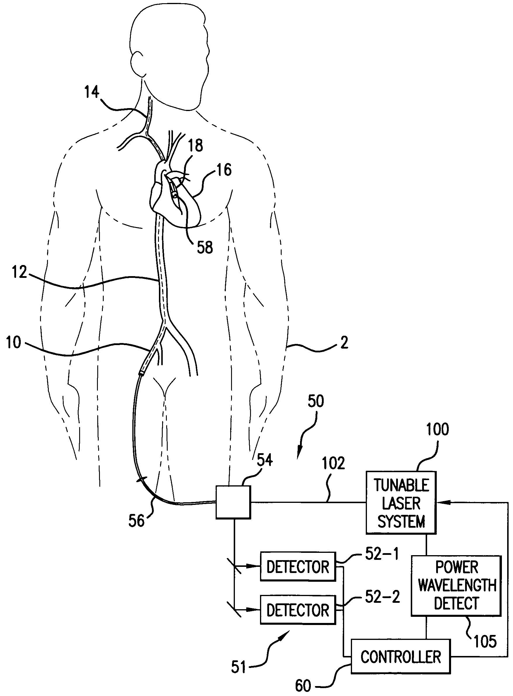
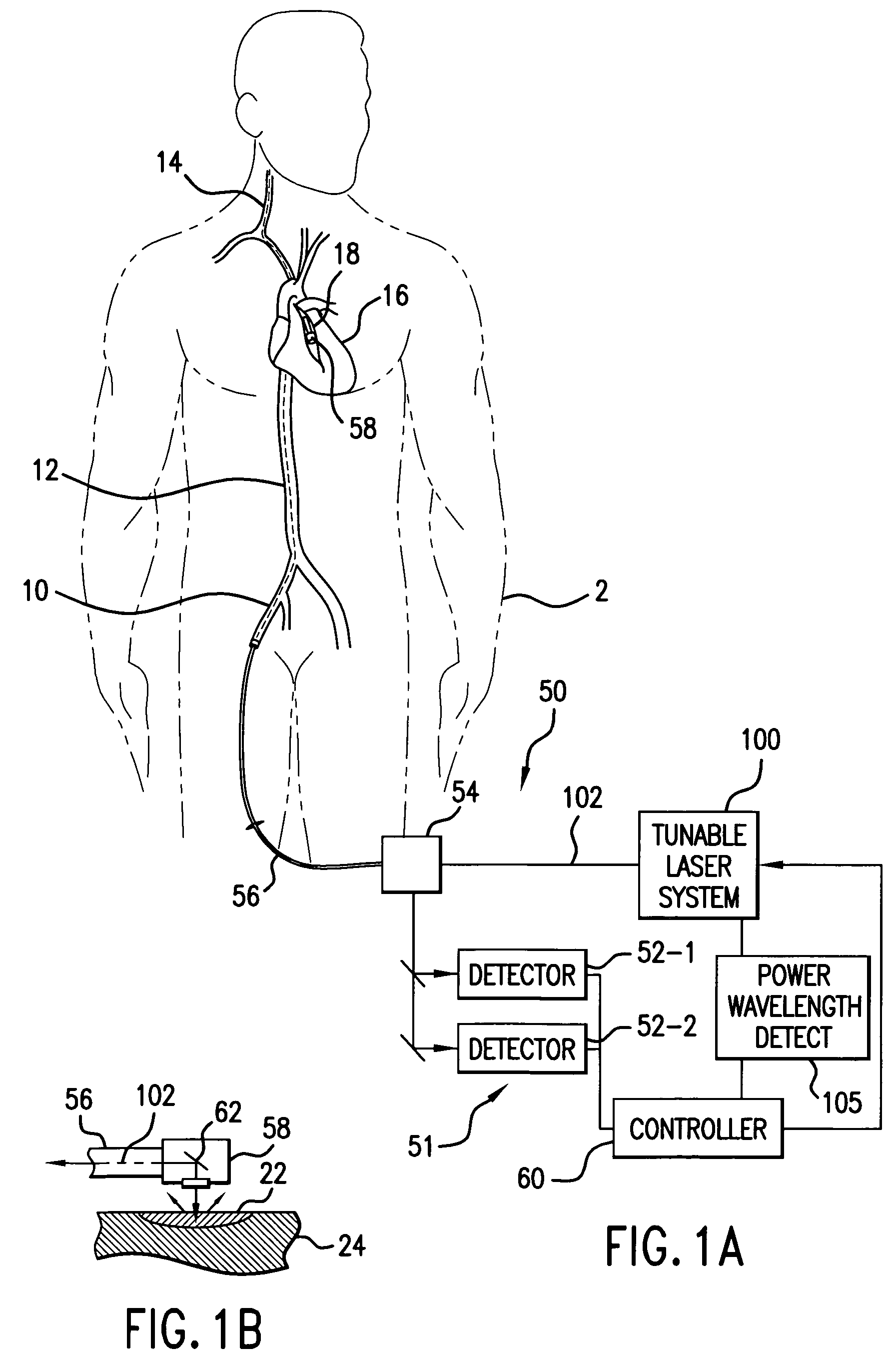
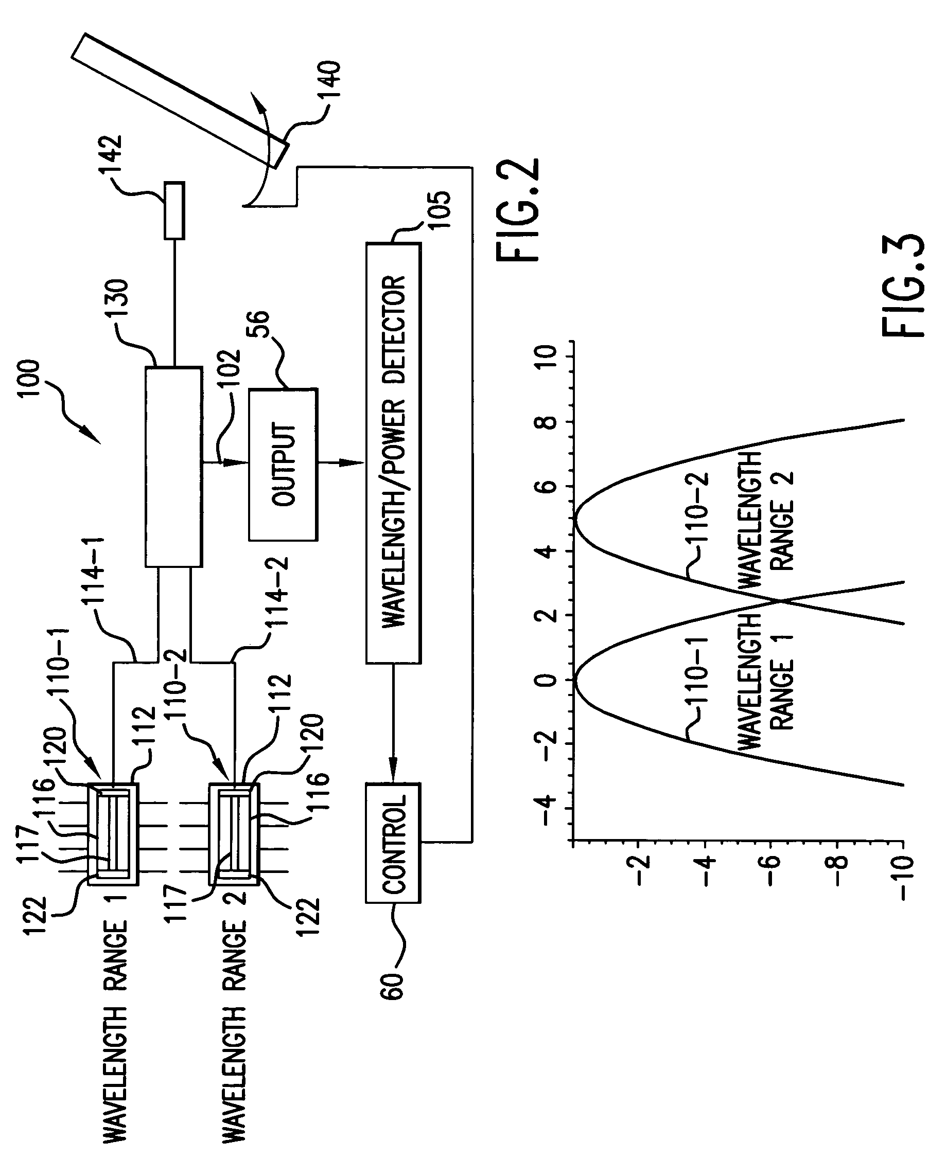
[0008]The present invention is directed to a laser system for a spectroscopic catheter system. The laser system uses multiple semiconductor gain media having gain peaks at different wavelengths. As a result, the laser oscillator source has a spectral output that is wider than the gain bandwidth of a single medium to enable it to access the entire spectrum of interest. The output from the gain media is preferably coupled into single-mode fiber using conventional, hermetic opto-electronic packaging techniques to provide a stable and controlled environment for long-term operation without performance degradation.
[0012]In the parallel architectures, multiple gain media are combined, and as the frequency selective element is tuned such that both gain media receive feedback simultaneously and in parallel. Thus, multiple spectral lasing peaks will appear at the output, and as the frequency selective element is tuned these peaks will be scanned simultaneously allowing access to multiple wavelength regions. Approaches for combining the gain media include using a frequency selective mirror (WDM), and offsetting the angle of incidence of the light sources on a diffraction grating.
[0016]The at least two SOA chips have different gain bandwidths. As a result, they can work cooperatively to increase the spectral bandwidth of the system over the bandwidth of a single element or chip.
[0025]The present invention provides a number of advantages over other solutions. First, it can be low cost and mass-produced since it leverages technologies available for the telecommunications industry. Moreover, these hermetic modules can be small and exhibit highly stable operation over wide ambient temperature ranges and time.

Problems solved by technology

Few existing technologies, however, can provide an optical signal that is tunable across such a large wavelength range and yet be compact, stable, and cost-effective.
Semiconductor sources are relatively inexpensive, efficient, and small, but the gain bandwidths of optical amplifiers, for example, are limited to 0.1 to 100 nm, depending upon the particular material system used to fabricate the chips.

Method used


Image

  • Spectroscopic catheter system with widely tunable source and method of operation
  • Spectroscopic catheter system with widely tunable source and method of operation
  • Spectroscopic catheter system with widely tunable source and method of operation

Examples


first embodiment

[0066]During operation, the first embodiment is tuned by progressively controlling the tilt of the frequency selective tunable element 140. As its feedback passes through the gain bandwidth of the SOA chip of first module 110-1, the first module provides the optical gain in the laser cavity. Then, as the frequency selective tunable element rotates further, its feedback passes through the gain bandwidth of the second module 110-2, which then provides the gain to the cavity.

[0067]FIG. 7 shows a second specific embodiment of the tunable laser source 100, which uses polarization diversity to achieve a low loss combination of the outputs from the two modules. The fiber pigtails 114-1, 114-2 from the modules 110-1, 110-2 comprise polarization-maintaining (PM) fiber. This fiber maintains the polarization state of the typically highly polarized energy from the chips 117 of the modules 110-1, 110-2.

[0068]One of the pigtails 114-1, 114-2 has an axis that is rotated 90 degrees with respect to ...

fourth embodiment

[0070]FIG. 9 shows the optical laser source 100. In this example, a WDM combiner 152 is used to combine and split the optical signals on the pigtails 114-1, 114-2 from the modules 110-1, 110-2. WDM combiner 152 is typically a thin film dichroic filter. It uses the spectrally distributed outputs from the two modules 110-1, 110-2 to combine their respective optical signals. A splitter / output coupler 130 couples to the frequency selectable tunable element 140 via the free space collimator 142 and provides the tap for the output signal 102.

[0071]The fourth embodiment has spectral dead zone due to the transition in the WDM filter 152. This dead zone will typically consume about 0.5 nanometers of the tuning curve. Further, power can be doubled by polarization combining two modules for each wavelength band.

fifth embodiment

[0072]FIG. 10 illustrates the tunable laser system 100. In this example, a one-by-two switch 154 is used to select one of modules 110-1, 110-2, and provide its output to a splitter / output coupler 130. In this example, only one of the laser modules 110-1, 110-2, is providing the gain to the laser cavity at any moment during operation.

[0073]In other embodiments, where additional modules combined, this system can be scaled to wider bandwidths of operation by increasing the port count of the switch 154 to a one-by-n switch, where n equals the number of modules.

[0074]The fifth embodiment, however, provides a non-zero switching time of a few milliseconds due to the operation of the switch 154. This creates a limited spectral dead zone. On the other hand, power can be doubled by polarization combining the output from two modules at each switch port.


PUM


Abstract

A laser system for a spectroscopic catheter system uses multiple semiconductor gain media having gain peaks at different wavelengths. The output from the gain media is preferably coupled into single-mode fiber using conventional opto-electronic packaging techniques. As a result, the laser oscillator source has a spectral output that is wider than the gain bandwidth of a single medium to enable it to access the entire spectrum of interest, which is presently in the near infrared. Moreover, the semiconductor gain media can be packaged in a stable and controlled environment for long-term performance.

Description

BACKGROUND OF THE INVENTION[0001]Tunable laser sources are applicable to a number of diagnostic and therapeutic medical applications. Optical coherence tomography is used to provide spatial resolution, enabling the imaging of internal structures. Spectroscopy is used to characterize the composition of structures, enabling the diagnosis of medical conditions, by differentiating between cancerous, dysplastic, and normal cellular structures. Fluorescence and exogenous chromospores can be used to increase the signal to noise ratio in these processes, providing for more accurate diagnostics.[0002]One specific example of an application for spectroscopy concerns atherosclerosis. This is an arterial disorder involving the intimae of medium- or large-sized arteries, including the aortic, carotid, coronary, and cerebral arteries. Atherosclerotic lesions or plaques contain a complex tissue matrix, including collagen, elastin, proteoglycans, and extracellular and intracellular lipids with foamy...

Claims


Application Information

Patent Timeline
IPC IPC(8): H01S3/00A61B5/00H01S5/0683H01S5/0687H01S5/14H01S5/40
CPCA61B5/0075A61B5/0084A61B5/0086H01S5/0683H01S5/0687H01S5/141H01S5/146H01S5/4062H01S5/4087
Inventor KORN, JEFFREY A.
Owner INFRAREDX INC
Learn More