


Quick Research
Generate reliable direction feasibility study reports for your R&D in just a few steps.

Technical Q&A
Discover and master advanced knowledge NOW. Basics, ideas, possibilities, all at once.

Find Solutions
As an expert in R&D theories, this can generate solutions to your technical problems instantly.

Evaluate Feasibility
Analyze your overall solution with one click, know your potential R&D risks in advance.

Monitor Landscape
Get weekly tech updates, stay abreast of the latest tech innovations and key insights.
Downdraft gasifier with improved stability
a gasifier and stability technology, applied in the direction of combustible gas production, lighting and heating apparatus, combustion types, etc., can solve the problems of need to shut down the gasifier, excessive pressure drop across the depth of the bed, and inability to distribute air evenly through the bed, etc., to achieve the effect of improving the stability of the downdraft gasifier and achieving higher energy output rates
- Summary
- Abstract
- Description
- Claims
- Application Information
AI Technical Summary
Benefits of technology
Problems solved by technology
Method used
Image

Examples
example 1
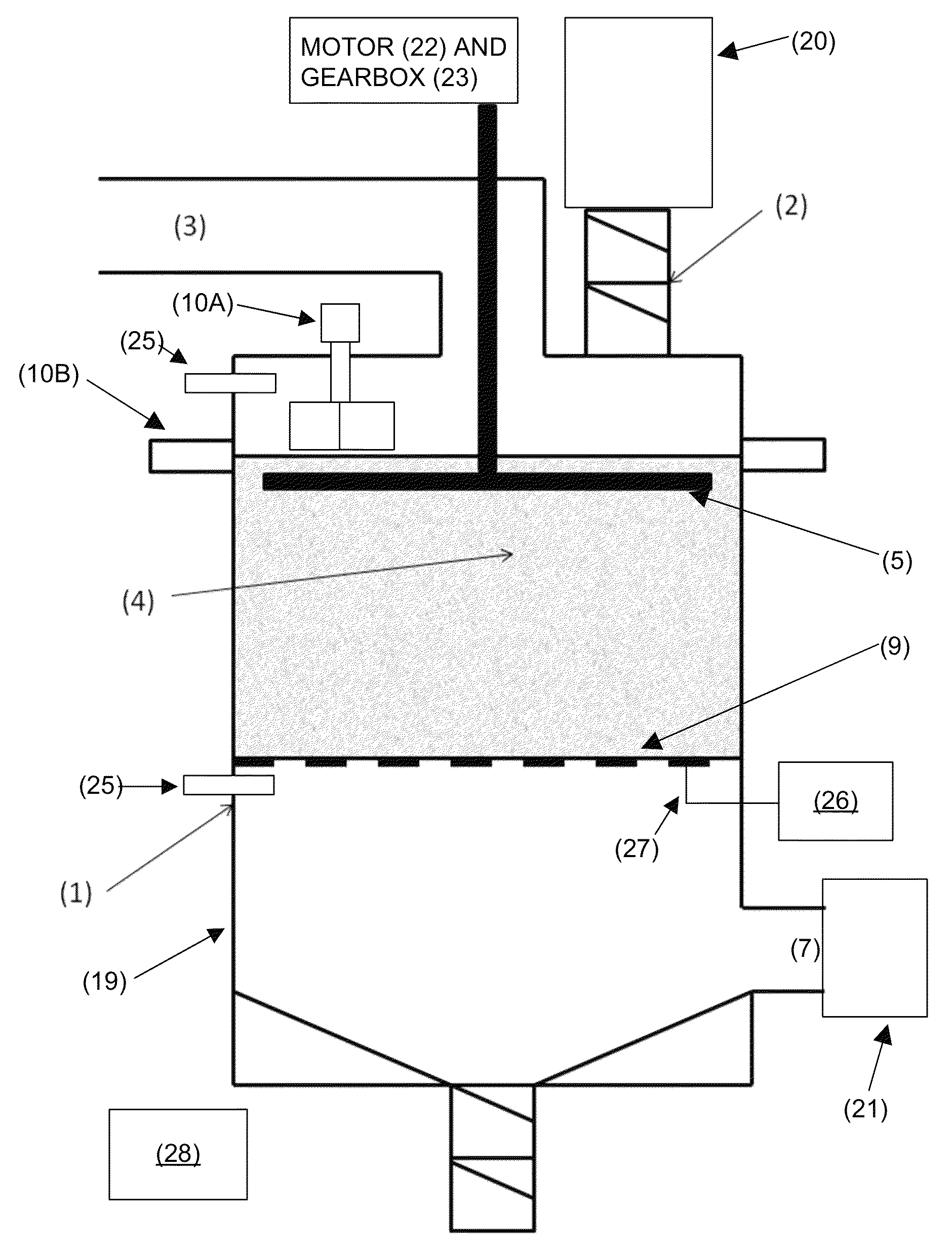
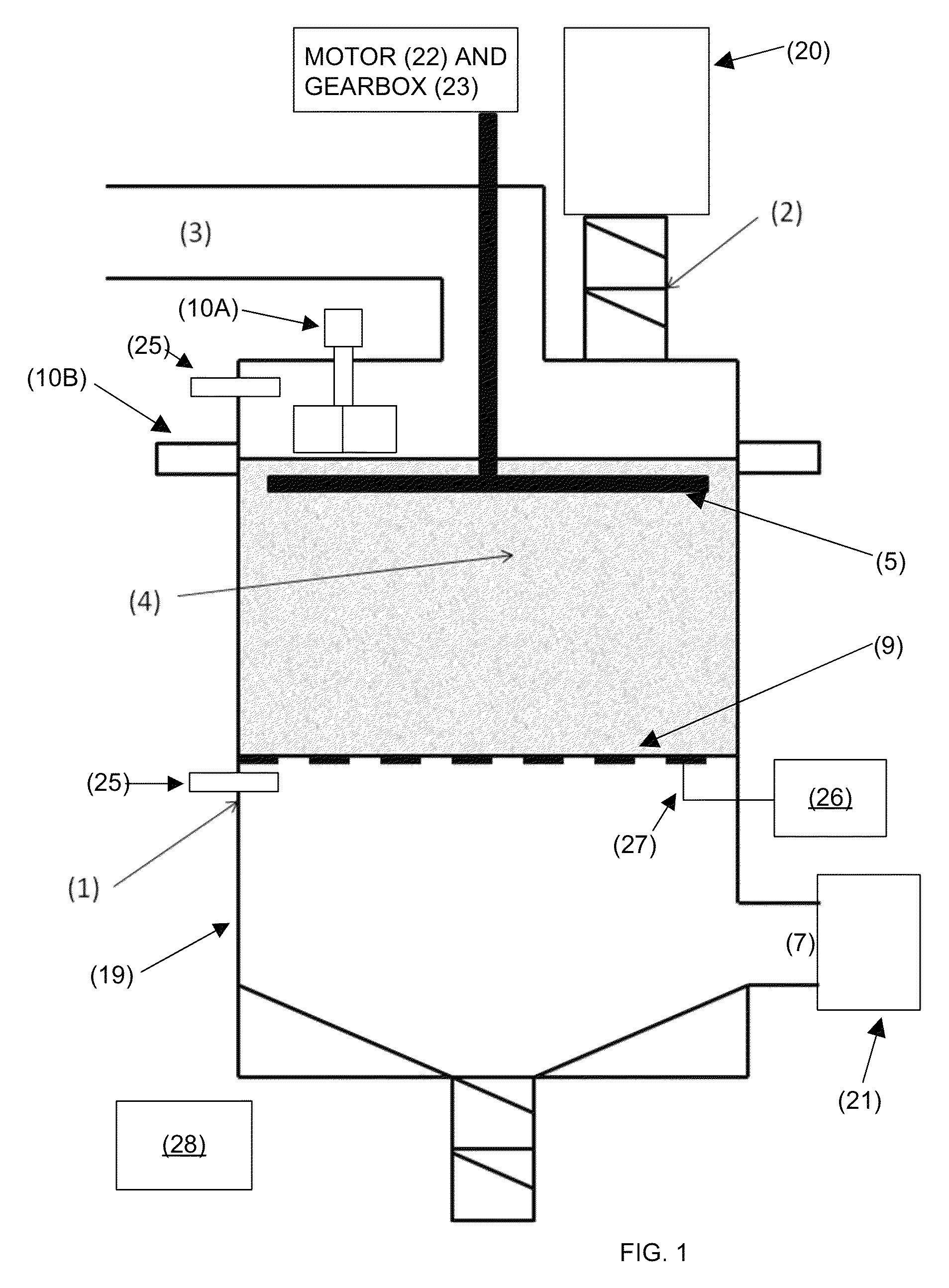
[0032]A 50″ inner diameter (ID) stratified gasifier with off center 12″ twin flap valves for biomass addition and a 6″ central air oxidant inlet was used to gasify ¼″ outer diameter (OD) wood pellets. A tangential laser system (10B) was used to indicate bed height and set to maintain the bed height at 24″ from the top of the grate (9) to the top of the bed. A laser system is not preferred because dust created when new material is added may temporarily give an erroneous height indication. Preferably, an infrared or microwave sensor would be used. Even more preferably, a rotary paddle switch (10A) would be used. An exemplary rotary paddle switch is a K-TEK Model KP Rotating Paddle Switch. Other rotary paddle switches may also be used. The signal from the laser was fed into a PLC system (28) which fed an auger system (not shown) to load the hopper (20) above the flap valves (2) and then initiate the flap valve sequence. A blower (21) was used to create a vacuum on the gasifier outlet t...
example 2
[0033]The same test as described above was conducted utilizing wood chips as the fuel source. The system was found to be more unstable than the test described in Example 1. After the test a large peak was found under the biomass feed point. Again damage had occurred to the grate under low points in the bed.
example 3
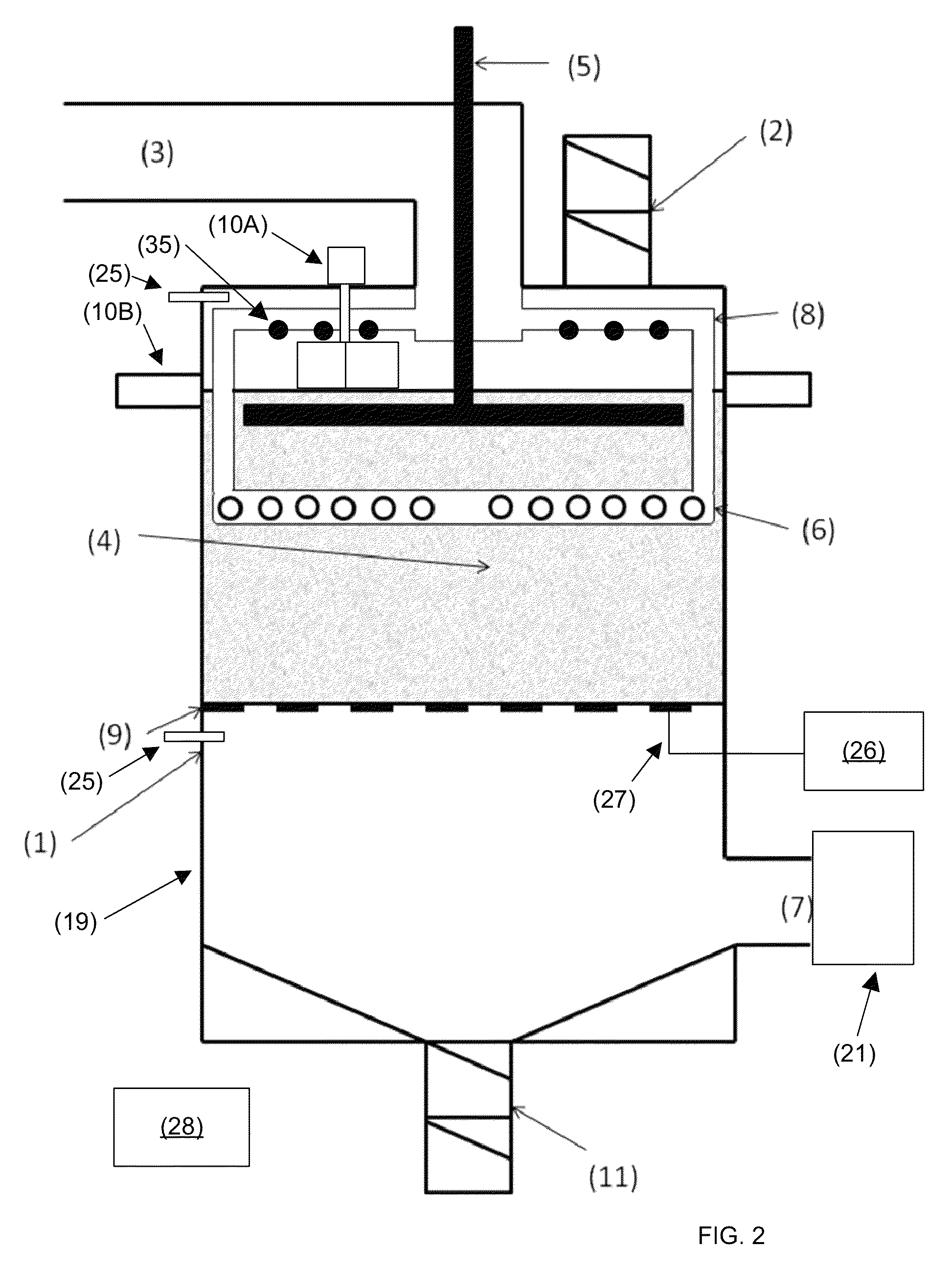
[0034]A rotating paddle arrangement (5) was installed in the 50″ ID gasifier described above. The system was externally driven using an electrical motor (22) and gearbox (23) arrangement. The motor was powered from a variable frequency drive (VFD) (not shown, but could be part of PLC (28)) to allow the effect of rotational speed to be investigated. The paddle (5) consisted of a solid 1″ 304 stainless steel square bar which was connected via a yoke arrangement (not shown) to the drive shaft (not separately numbered). The paddle was arranged such that the top of the paddle was 1″ below the level of the bed indicator laser (10). The paddle was set to rotate at approximately 1 RPM. The test described in Example 1 was repeated. The system was found to operate in a stable manner with consistent radial temperature profiles. A strong syngas was produced which showed little variation over the entire period (50 minutes) of the test. The system was operated for four hours after which time the ...
PUM
| Property | Measurement | Unit |
|---|---|---|
| operating temperature | aaaaa | aaaaa |
| velocity | aaaaa | aaaaa |
| velocity | aaaaa | aaaaa |
Abstract
Description
Claims
Application Information
 - R&D Engineer
- R&D Manager
- IP Professional
- Industry Leading Data Capabilities
- Powerful AI technology
- Patent DNA Extraction
Browse by: Latest US Patents, China's latest patents, Technical Efficacy Thesaurus, Application Domain, Technology Topic, Popular Technical Reports.
© 2024 PatSnap. All rights reserved.Legal|Privacy policy|Modern Slavery Act Transparency Statement|Sitemap|About US| Contact US: help@patsnap.com