
Leakage compensation for switched capacitor integrators

a switched capacitor and integrator technology, applied in the field of leakage compensation of switched capacitor integrators, can solve the problems of finite amplifier gain, flicker noise, imperfections,

Active Publication Date: 2014-09-23
ANALOG DEVICES INT UNLTD
View PDF7 Cites 8 Cited by
  • Summary
  • Abstract
  • Description
  • Claims
  • Application Information

AI Technical Summary

Benefits of technology

The patent text describes a technique called correlated double sampling (CDS) that improves the accuracy of analog-to-digital converters (ADCs) by removing unwanted offsets. However, the CDS technique can be negatively affected by parasitic capacitances in the integration switches, which can cause leakage and limit the resolution of the ADCs. The patent text proposes a solution to mitigate the effects of parasitic capacitances and improve the accuracy of CDS-based ADCs.

Problems solved by technology

Although present switched-capacitor gain circuits generally perform their function, they do have imperfections.
For example, flicker noise, finite gain of the amplifier, and DC offsets detrimentally affect the achievable accuracy of switched-capacitor gain circuits.
Although CDS techniques may improve the achievable accuracy of switched capacitor circuits, they come at a cost.
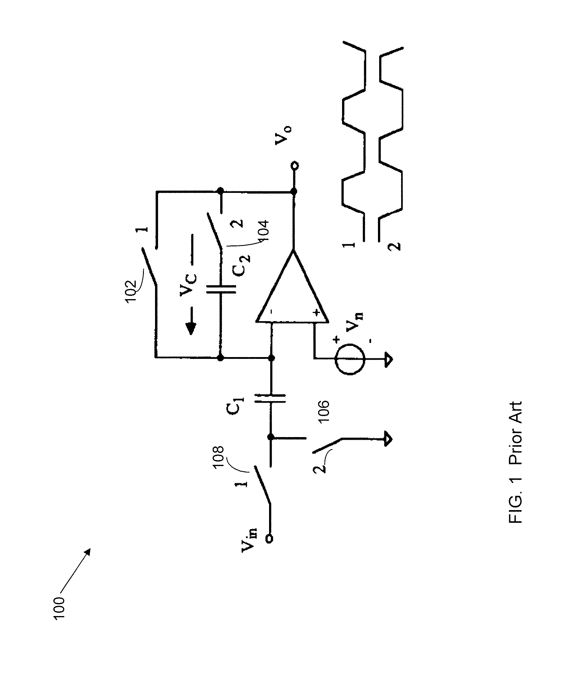
Parasitic capacitances of the prior art integration switches may cause leaky integrators that limit the maximum achievable resolution of Analog-to-Digital Converters (ADCs), such as sigma delta ADCs.
First order sigma delta converters are more susceptible to integrator leakage than higher order modulators.
Integrator leakage results in dead zones of the ADC transfer curve.
For example, large integral non-linearity (INS) errors may be introduced due to the leakage currents.
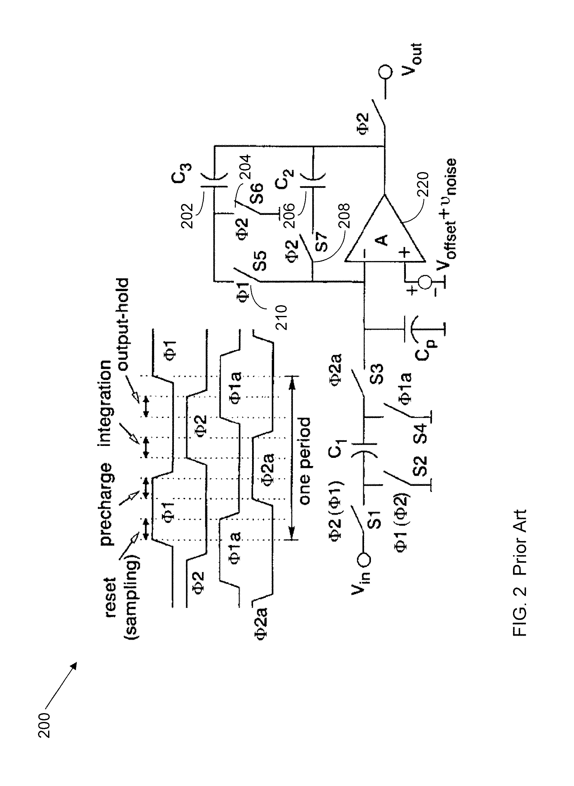
In phase 2, the capacitor 202 additionally loads the output of the amplifier 220, thereby causing bandwidth constraints when used with single stage amplifiers.
Traditional ways of addressing this concern resulted in more complex circuits that use more real estate by including an additional capacitor of the same size as the integration capacitor, an offset storing capacitor, and / or a much larger number of active sampling switches.

Method used


Image

  • Leakage compensation for switched capacitor integrators
  • Leakage compensation for switched capacitor integrators
  • Leakage compensation for switched capacitor integrators

Examples


Embodiment Construction

[0021]In the following detailed description, numerous specific details are set forth by way of examples in order to provide a thorough understanding of the relevant teachings. However, it should be apparent that the present teachings may be practiced without such details. In other instances, well-known methods, procedures, components, and / or circuitry have been described at a relatively high-level, without detail, in order to avoid unnecessarily obscuring aspects of the present teachings.

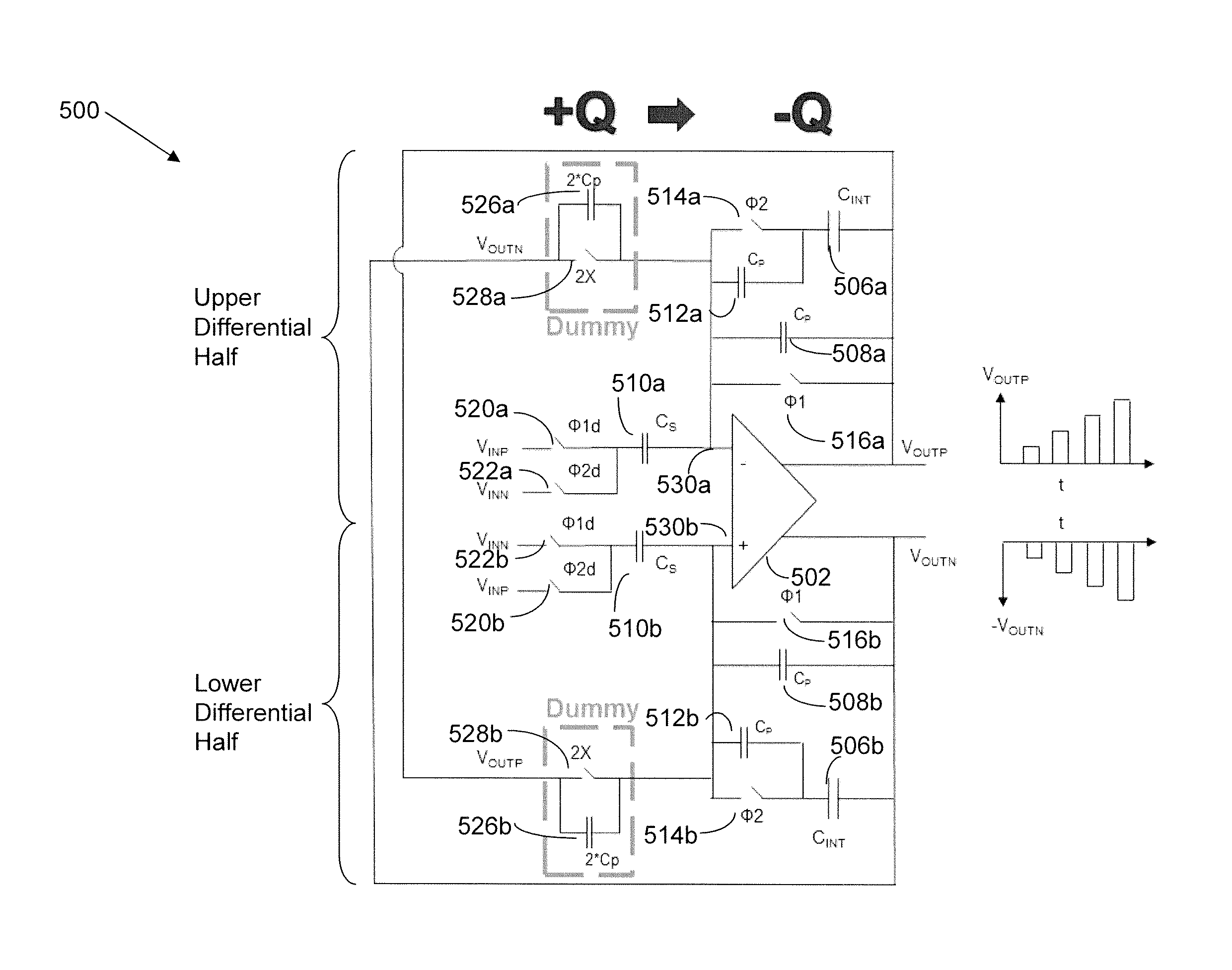
[0022]The various methods and circuits disclosed herein relate to differential CDS switched capacitor (SC) integrator circuits that compensate for leakage in the integration capacitor. In accordance with one aspect of the present disclosure, the circuit includes a differential amplifier having inverting and non-inverting inputs and positive and negative outputs. First and second integration capacitors are respectively coupled to the positive and negative outputs. The differential amplifier has a fir...


PUM


Abstract

Methods and systems for a differential correlated double sampling (CDS) switched capacitor integrator circuit. The circuit includes a differential amplifier that has a differential input and a differential output. There is a first feedback path between the negative output node and the positive input node, and a second feedback path between the positive output node and the negative input node. Each feedback path includes an integration capacitor and at least one switch that has a parasitic capacitance. A first capacitive element is coupled between the negative input node and the negative output node, and a second capacitive element is coupled between the positive input node and the positive output node. Each capacitive element is configured to cancel the parasitic capacitance of its corresponding feedback path.

Description

TECHNICAL FIELD[0001]This disclosure relates to switched capacitor (SC) circuits, and more particularly, to a correlated double sampling (CDS) switched capacitor integrator.DESCRIPTION OF RELATED ART[0002]In recent years there has been an effort to improve methods of and circuits for acquiring analog signals and converting them to the digital domain. Although real world signals are analog, it is often desirable to convert them to the digital domain using analog-to-digital converters (ADCs). For example, sampling systems are frequently found in popular consumer electronic devices such as MP3 players, DVD players and cellular telephones. Other popular uses of sampling systems include those related to data acquisition, test and measurement, and control system applications. Sampling systems and sample-based technology may be found in the electronic components used to construct such devices, which include analog-to-digital converters, switched capacitor networks, signal acquisition circu...

Claims


Application Information

Patent Timeline
Patent Type & Authority Patents(United States)
IPC IPC(8): H03K5/00H03F1/34
CPCH03F1/34H03F2203/45514H03M3/00H03F3/45475
Inventor TRAMPITSCH, GERD
Owner ANALOG DEVICES INT UNLTD
Learn More