
Communication system and method for directly transmitting signals between nodes of a communication system

a communication system and communication system technology, applied in the field of communication systems, can solve the problems of large processing burden of the central gateway (the central switching unit b>100/b>), inability to meet the requirements of x2 interface latency and capacity, and limited bandwidth, so as to achieve higher user throughput, reduce latency, and increase capacity

Inactive Publication Date: 2014-09-16
NTT DOCOMO INC
View PDF17 Cites 2 Cited by
  • Summary
  • Abstract
  • Description
  • Claims
  • Application Information

AI Technical Summary

Benefits of technology

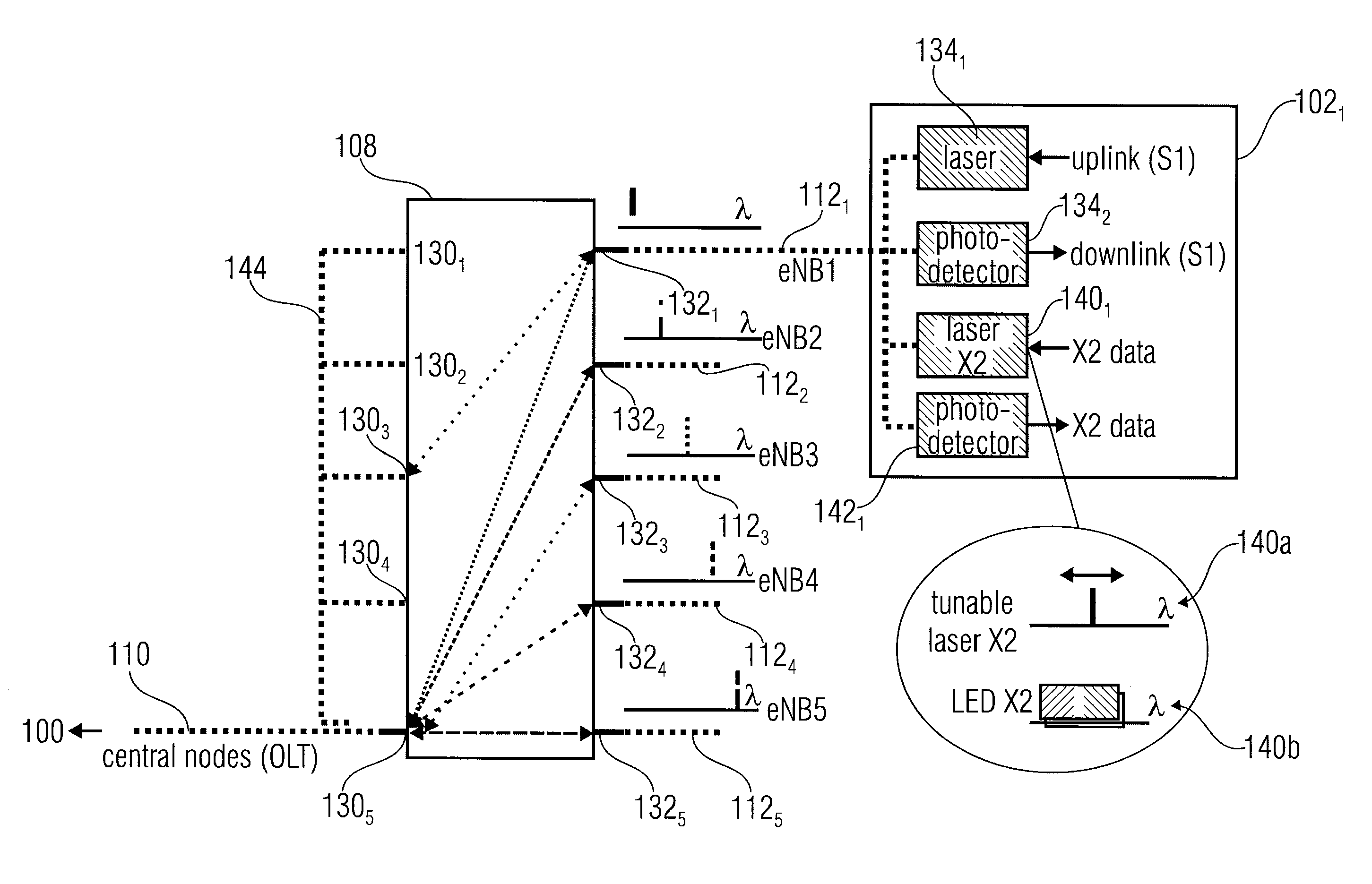
The invention provides a way to use a coordinated multipoint (CoMP) transmission / reception technique in LTE-advanced applications by utilizing a mobile backhaul access network with a physical X2 interface. This interface offers a larger capacity and a lower latency compared to conventional logical interfaces, which is advantageous for CoMP techniques. The invention also provides a cost-effective solution as it uses previously deployed low loss fiber networks, reducing the need for additional system hardware and frequency licenses. The invention is a mobile backhaul WDM-PON access network with a physical X2 interface for CoMP applications, which allows for a direct exchange of information between base stations at a sufficient data rate and low latency. The WDM-PON access network is favorable for new generation mobile networks needing a "direct" exchange of information between base stations. The invention provides a novel WDM-PON system supporting not only point-to-point communication, but also a broadcasting communication among the nodes.

Problems solved by technology

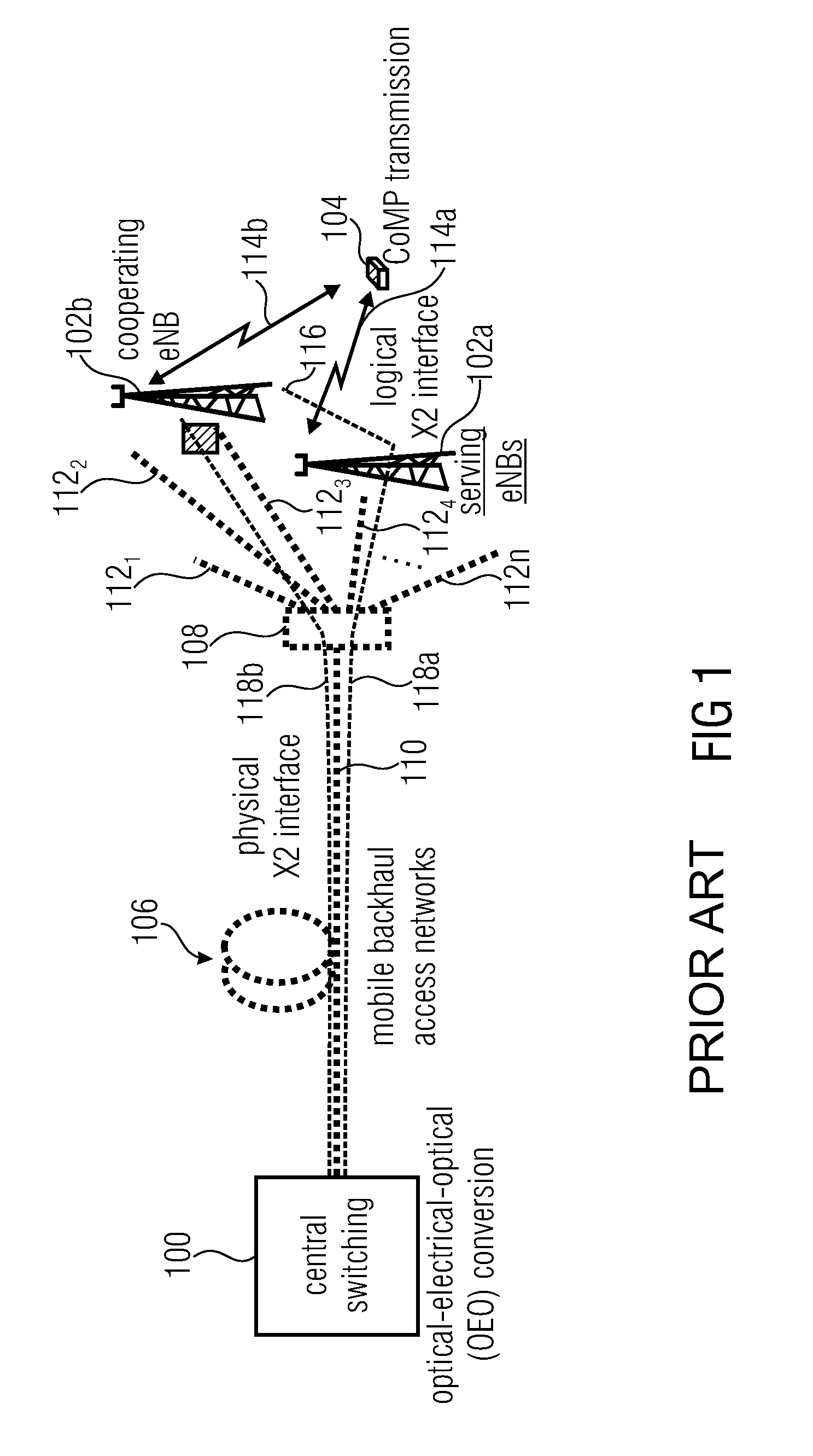
While this may minimize or reduce hardware costs, it results in the problem that the latency and the capacity of the X2 interface may not fulfill the requirements for information exchange in accordance with the CoMP scheme.
In addition, a large processing burden for the central gateway (the central switching unit 100) exists due to the additional OEO conversion.
Further, since the X2 interface shares the physical link with the S1-U interface only limited bandwidth is available.
However, when implementing a CoMP transmission the latency and the limited capacity of the X2 interface realized in a way as shown in FIG. 1 form a bottleneck for CoMP, since, in general, a CoMP transmission needs less than a few ms latency and a true Gbps traffic for the inter-eNBs communication (the communication between the respective base stations).
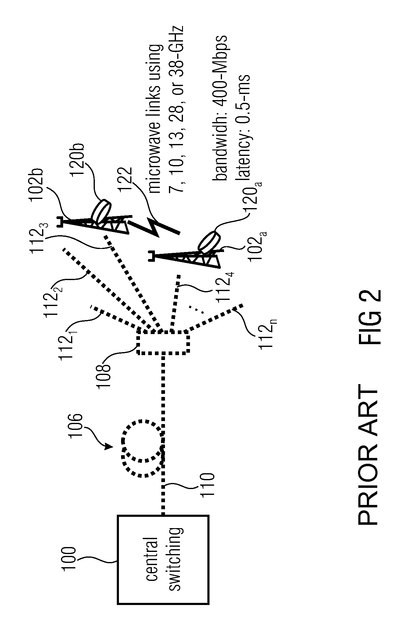
However, it is not practical to deploy additional fiber links for the X2 interface due to the associated costs.
However, providing the X2 physical link by installing a microwave / millimeter-wave point-to-point link between two base stations is a very expensive solution as it needs a huge number of additional hardware for the wireless backhauls to cover all nodes.
Also, the link typically does not offer as much link quality as the backhaul fiber-optic link due to its susceptibility to the environment, e.g. the weather conditions.
However, only broadcasting of signals is possible, i.e. no point-to-point communication is possible, as it is needed for a direct communication link between respective base stations or nodes (e.g. needed by the X2 interface).
In addition, using the plurality of splitter boxes increases the costs and reduces the SNR (signal-to-noise ratio), which is a problem with regard to the transmission in the Gbps range.
In addition, due to the splitting ratio the loss of a large amount of signal-to-noise ratio cannot be avoided thereby limiting the data rate in the X2 interface so that the TDM-PON cannot support more that 1-Gbps bandwidth per node.

Method used


Image

  • Communication system and method for directly transmitting signals between nodes of a communication system
  • Communication system and method for directly transmitting signals between nodes of a communication system
  • Communication system and method for directly transmitting signals between nodes of a communication system

Examples


Embodiment Construction

[0051]On the basis of FIG. 3, the differences between a TDM-PON and a WDM-PON are discussed. FIG. 3A shows a schematic representation of a time division multiplexing passive optical network (TDM-PON). The TDM-PON comprises the central switching unit 100 (OLT=optical line terminal) and the splitter 108 coupled to the OLT 100 via the connection 110, which is a fiber optic connection. The splitter 108 is further connected to a plurality base stations (ONU=optical network unit) 1021 to 102n. Each of the optical network units 1021 to 102n is connected to the splitter 108 via a respective branch connection 1121 to 112n formed of respective optical fibers. The splitter 108 may be a 1:32 splitter, meaning that 32 different optical network units 1021 to 102n may be serviced, i.e. n=32. The TDM-PON operates in a wavelength range of 1260-1280 nm for the uplink or upstream connection, i.e. for transmitting data from one or more of the optical network units 1021to 102n to the optical line termin...


PUM


Abstract

A communication system has a plurality of nodes adapted to provide for a communication with one or more devices, a central node, a passive optical network having a multiplexer / demultiplexer device adapted to demultiplex a first optical signal from the central node to the plurality of nodes, and to multiplex second optical signals from one or more of the nodes, each node having allocated a wavelength for generating its optical signal, wherein for directly transmitting signals from one node to at least one of the other nodes, the one node is adapted to generate an optical signal at the wavelength allocated to the at least one of the other nodes, the optical signal including the signal to be transmitted, and wherein the multiplexer / demultiplexer device of the passive optical network is adapted to combine the optical signal from the one node with the first optical signal.

Description

RELATED APPLICATIONS[0001]This application claims priority under 35 U.S.C. §119 to European Patent Application No. 11150495.7 filed on Jan. 10, 2011, the entire content of which is hereby incorporated by reference.BACKGROUND OF THE INVENTION[0002]Embodiments of the invention concern the field of communication systems, for example, mobile communication systems comprising a plurality of base stations serving respective mobile units. More specifically, embodiments of the invention refer to a communication system and a method for directly allowing a communication among respective nodes thereof, for example among respective base stations, as well as to a node or base station and an optical multiplexer / demultiplexer device of such a communication system.[0003]In a communication system a plurality of nodes and a central switching device are coupled via a backhaul access network for exchanging signals between the nodes. However, there may be circumstances that need the exchange of informati...

Claims


Application Information

Patent Timeline
Patent Type & Authority Patents(United States)
IPC IPC(8): H04J14/00H04B10/00H04B10/2581H04B10/272H04J14/02
CPCH04J14/0246H04J14/0235H04J14/025H04J14/02H04B10/00
Inventor CHOI, CHANGSOONWEI, QINGBIERMANN, THORSTEN
Owner NTT DOCOMO INC
Learn More