
Gas-barrier heat-seal composite films and vacuum insulation panels comprising the same

a technology of which is applied in the field of gas-barrier heat-seal composite films and vacuum insulation panels, can solve the problems of not coming close to meeting gas barrier requirements, unable to be applied easily, and not allowing gas to pass thereto, etc., to achieve high gas barrier, improve metal adhesion and gas barrier effects, and improve the effect of gas barrier

Active Publication Date: 2014-06-10
IND TECH RES INST
View PDF10 Cites 10 Cited by
  • Summary
  • Abstract
  • Description
  • Claims
  • Application Information

AI Technical Summary

Benefits of technology

The composite film achieves a high gas barrier, flexibility, light weight, and recyclability, with improved metal adhesion and energy efficiency, suitable for vacuum insulation panels and food packaging, with oxygen and water vapor transmission rates below 0.01 cc / m²day·atm and heat-seal strength greater than 1,500 g / 25 mm, while reducing energy consumption and enabling carbon reduction.

Problems solved by technology

When the high-gas-barrier film material is utilized in a vacuum seal or a gas-barrier package, the effect of not allowing gas to notably pass thereto can last for several years.
Among the commonly used gas-barrier film materials, plastic film materials do not come close to meet gas barrier requirements.
Although glass materials have a high gas barrier, it cannot be applied easily due to its shortcomings of having an energy-consuming process, having no flexibility and having a heavy weight etc.
Metal film materials such as aluminum foil have the shortcomings of having an energy-consuming process and non-recyclability, and its high thermal conductivity makes it inappropriate for application in certain specific products (for example vacuum insulation panels).

Method used


Image

  • Gas-barrier heat-seal composite films and vacuum insulation panels comprising the same
  • Gas-barrier heat-seal composite films and vacuum insulation panels comprising the same
  • Gas-barrier heat-seal composite films and vacuum insulation panels comprising the same

Examples


example 1

Preparation of the Gas-Barrier Heat-Seal Composite Film (1)

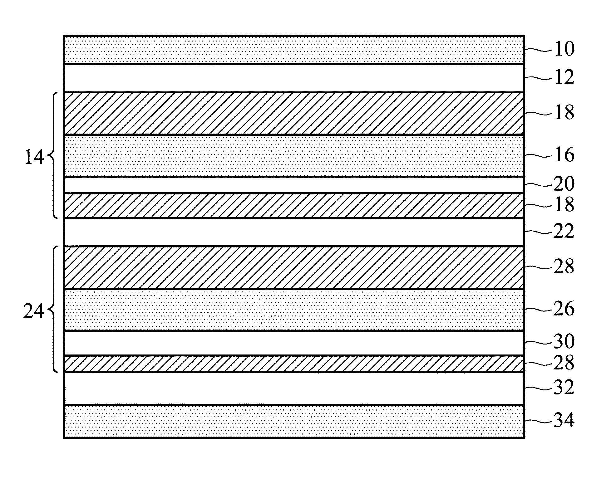
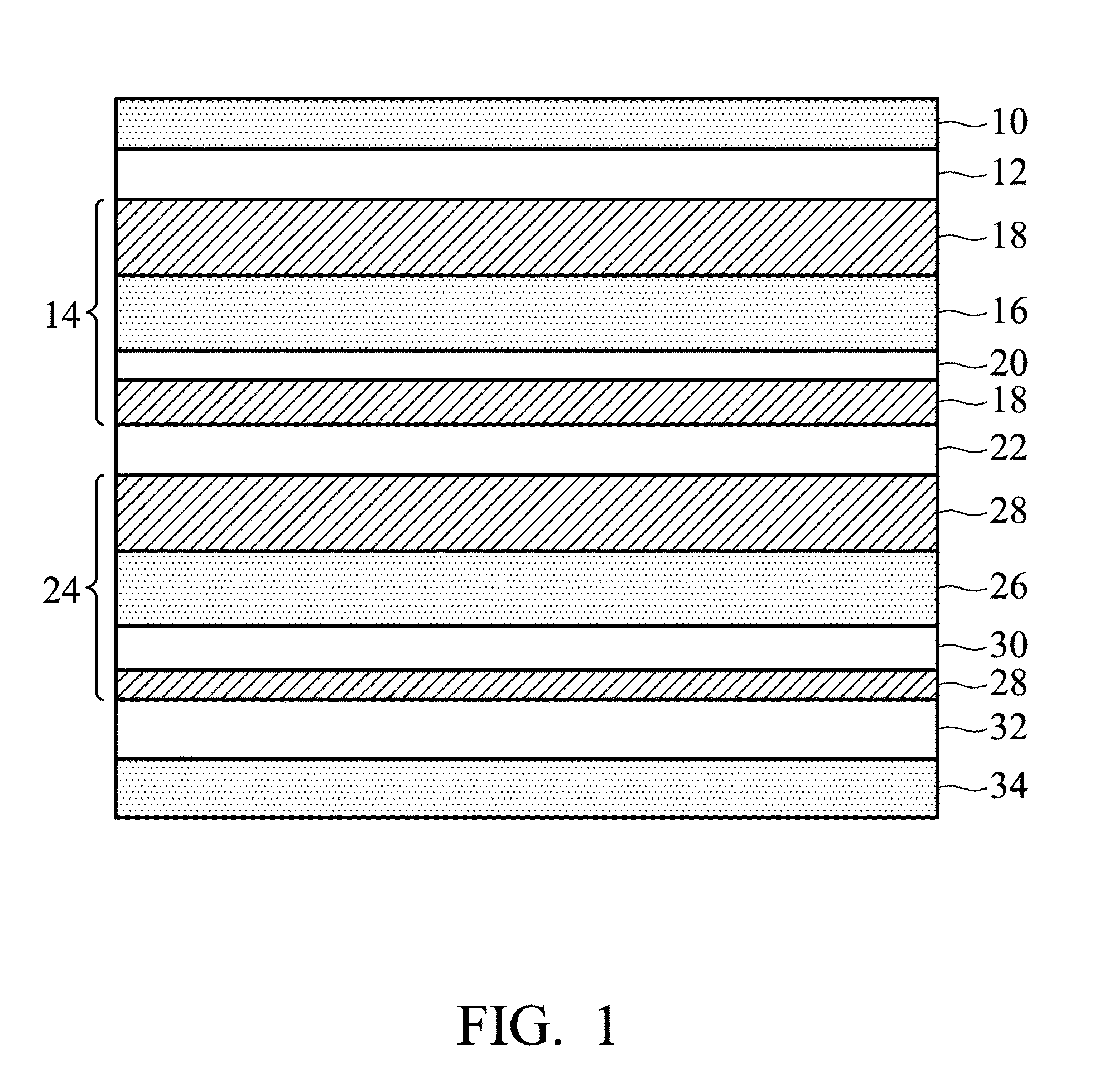
[0028]A multiple-layered composite film was prepared by the evaporation and binding method, as shown in FIG. 1. The composite film comprised, from top to bottom, a PET protective layer 10 (with a thickness of 13 μm), an epoxy resin glue 12 (with a thickness of 7 μm), a PET composite layer 14 (a PET substrate 16 with a thickness of 17 μm vacuum-metallized with two aluminum layers 18 with a respective thickness of 30 nm on both sides thereof, and a primer layer 20 with a thickness of 7 μm), an epoxy resin glue 22 (with a thickness of 7 μm), a PET composite layer 24 (a PET substrate 26 with a thickness of 17 μm plated with two aluminum layers 28 with a respective thickness of 30 nm on both sides thereof, and a primer layer 30 with a thickness of 7 μm), an epoxy resin glue 32 (with a thickness of 7 μm) and a PE heat-seal layer 34 (with a thickness of 60 μm). In this example, the oxygen transmission rate of the gas-barrier heat-s...

example 2

Preparation of the Gas-Barrier Heat-Seal Composite Film (2)

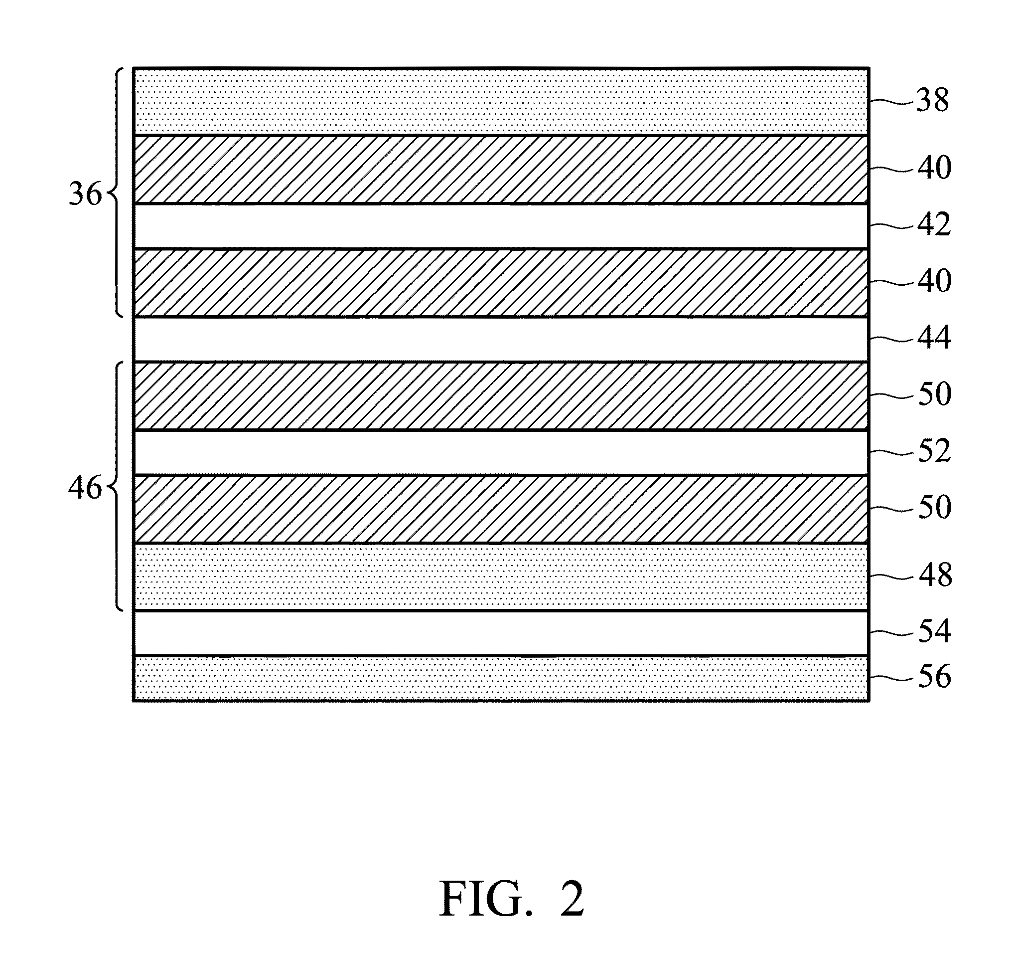
[0029]A multiple-layered composite film was prepared by the evaporation and binding method, as shown in FIG. 2. The composite film comprised, from top to bottom, a PET composite layer 36 (a PET substrate 38 with a thickness of 17 μm vacuum-metallized with two aluminum layers 40 with a respective thickness of 30 nm on one side thereof toward an epoxy resin glue 44, and a primer layer 42 with a thickness of 7 μm), the epoxy resin glue 44 (with a thickness of 7 μm), a PET composite layer 46 (a PET substrate 48 with a thickness of 17 μm vacuum-metallized with two aluminum layers 50 with a respective thickness of 30 nm on one side thereof toward an epoxy resin glue 44, and a primer layer 52 with a thickness of 7 μm), an epoxy resin glue 54 (with a thickness of 7 μm) and a EP-copolymer heat-seal layer 56 (with a thickness of 60 μm). In this example, the oxygen transmission rate of the gas-barrier heat-seal composite film was lower...

example 3

Preparation of the Gas-Barrier Heat-Seal Composite Film (3)

[0030]A multiple-layered composite film was prepared by the evaporation and binding method, as shown in FIG. 3. The composite film comprised, from top to bottom, a PET protective layer 58 (with a thickness of 13 μm), an epoxy resin glue 60 (with a thickness of 7 μm), a PET composite layer 62 (a PET substrate 64 with a thickness of 17 μm vacuum-metallized with two aluminum layers 66 with a respective thickness of 30 nm on both sides thereof, and a primer layer 68 with a thickness of 7 μm), an epoxy resin glue 70 (with a thickness of 7 μm), a EVOH composite layer 72 (a EVOH substrate 74 containing 44% ethylene with a thickness of 20 μm metallized with one aluminum layer 76 with a thickness of 30 nm on one side thereof toward the epoxy resin glue 70 bound with the metallized aluminum layer 76), an epoxy resin glue 78 (with a thickness of 7 μm) and a PE heat-seal layer 80 (with a thickness of 60 μm). In this example, the oxygen ...


PUM

PropertyMeasurementUnit
thicknessaaaaaaaaaa
thicknessaaaaaaaaaa
thicknessaaaaaaaaaa

Abstract

A gas-barrier heat-seal composite film is provided. The gas-barrier heat-seal composite film includes a heat-seal layer including very low density polyethylene (VLDPE), low density polyethylene (LDPE), linear low density polyethylene (LLDPE), high density polyethylene (HDPE), metallocene polyethylene (mPE), metallocene linear low density polyethylene (mLLDPE), ethylene vinyl acetate (EVA) copolymer, ethylene-propylene (EP) copolymer or ethylene-propylene-butene (EPB) terpolymer, and a gas-barrier layer formed on the heat-seal layer, wherein the gas-barrier layer includes a plurality of composite layers, each including a polymer substrate and a single layer or multiple layers of metal or oxide thereof which is formed on one side or both sides of the polymer substrate, and the polymer substrate includes uniaxial-stretched or biaxial-stretched polyethylene terephthalate (PET), polybutylene terephthalate (PBT), polyimide (PI), ethylene / vinyl alcohol (EVOH) copolymer or a combination thereof. The invention also provides a vacuum insulation panel including the composite film.

Description

CROSS REFERENCE TO RELATED APPLICATIONS[0001]This Application claims priority of Taiwan Patent Application No. 99142987, filed on Dec. 9, 2010, the entirety of which is incorporated by reference herein.BACKGROUND OF THE INVENTION[0002]1. Field of the Invention[0003]The invention relates to a gas-barrier heat-seal material, and in particular to a gas-barrier heat-seal composite film and a vacuum insulation panel comprising the composite film.[0004]2. Description of the Related Art[0005]A high-gas-barrier film material possesses a high gas barrier and flexibility. When the high-gas-barrier film material is utilized in a vacuum seal or a gas-barrier package, the effect of not allowing gas to notably pass thereto can last for several years. Among the commonly used gas-barrier film materials, plastic film materials do not come close to meet gas barrier requirements. Although glass materials have a high gas barrier, it cannot be applied easily due to its shortcomings of having an energy-c...

Claims


Application Information

Patent Timeline
Patent Type & Authority Patents(United States)
IPC IPC(8): B32B27/08B32B7/12B32B27/06
CPCB32B2307/304B32B5/18B32B2307/31B32B15/09B32B2307/7242B32B2307/514B32B15/08B32B27/36B32B2266/025B32B27/32B32B27/327B32B2255/06B32B2255/205B32B27/065B32B27/306B32B2255/20B32B2266/06B32B15/20B32B2266/0214B32B2266/0228B32B2607/00Y10T428/24Y10T428/2826Y10T428/2804Y10T428/265Y10T428/25Y10T428/263Y10T428/231Y10T428/264
Inventor HSU, JUI-HUNGKONG, DAN-CHENGWONG, CHANG-MING
Owner IND TECH RES INST
Learn More