Charged particle induction from ionosphere to ground

a technology of ionosphere and induction of charged particles, which is applied in the direction of electrostatic charges, emergency protective arrangement details, electrical equipment, etc., can solve the problems of increasing world demand, increasing the cost of petrochemical energy, and needing to develop alternative clean renewable energy supplies, etc., to achieve low resistance, resistance (and voltage drop), and safe control of lightning strike discharge

Active Publication Date: 2014-04-08
GLENN LANE FAMILY LIMITED LIABILITY
View PDF8 Cites 5 Cited by
  • Summary
  • Abstract
  • Description
  • Claims
  • Application Information

AI Technical Summary

Problems solved by technology

The need to develop alternative clean renewable energy supplies is becoming critical.
The dramatic rise in the cost of petro-chemical energy is due to decreased supplies and increase in world demand.
There is increasing political instability of regions of the world that have large oil supplies.
Space solar power is clean, inexhaustible, available 24 hours a day, and has the potential to generate as much energy as terrestrial power plants.
However, because of the filtering effect of the Earth's atmospheric gases (air acts as an insulator), and for other reasons such as reflection and absorption, only a fraction of solar energy in any given area reaches Earth.
Since wires extending from Earth's surface to an orbiting satellite would be impractical, many space-based solar power designs have proposed the use of microwave or laser beams for wireless power transmission.
There are numerous technical, political, legal and economic challenges to building space solar power stations.
Limitations in photovoltaic technology and the difficulty of building large structures in space are some of the issues.
In the past, launch costs have been prohibitive.
In addition to the relatively high costs involved with this method, other problems include cumulative radiation damage or micrometeoroid impacts.
Ideally, a wireless power transmission system would have the ability to transmit any amount of power to any point in space, but practical limitations such as conversion efficiencies at the source and the receiver, and disturbances in the transmission medium will always limit the performance of an implemented system.
Although these experiments confirm that the VMJ technology can withstand and utilize the high intensity laser energy without damage or significant reduction in previously known conversion efficiencies, wireless power transmission via high intensity laser beaming technology is not yet ready for high order energy transfer.
In short, the main limiting factors to the laser power beaming system are the conversion efficiencies of the laser (electrical to photonic) and the photovoltaic cells (photonic to electrical).
Although there are a variety of photovoltaic cells on the market approaching conversion efficiencies of 40% (such as triple junction cells), these technologies cannot operate at intensities 1000 times or greater than that of the sun.
Based on the above, it is clear that there is a strong desire to harness the energy existing in both our atmosphere and beyond, but it is apparent that the various methods and apparatus designed to capture and utilize this energy source are attendant with various, problems, shortcomings and limitations.

Method used


Image

  • Charged particle induction from ionosphere to ground
  • Charged particle induction from ionosphere to ground
  • Charged particle induction from ionosphere to ground

Examples


Embodiment Construction

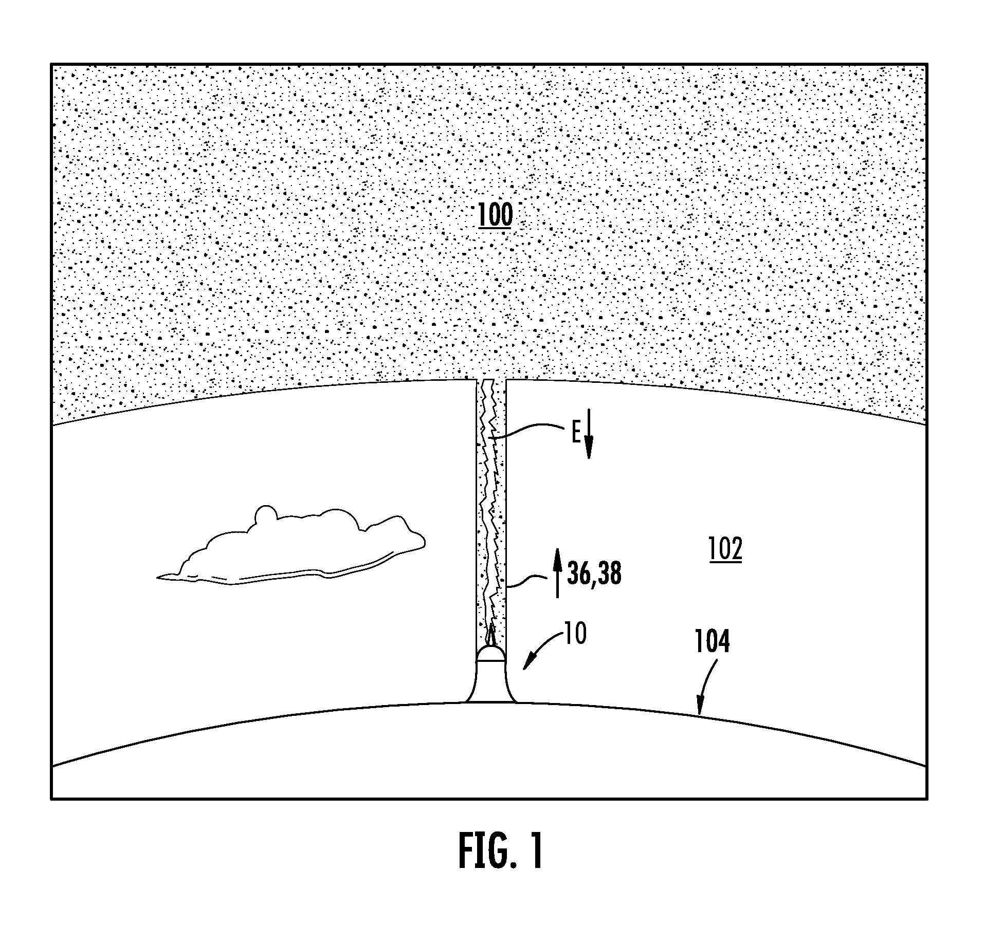
[0025]Reference is now made to FIG. 1 in which there is illustrated a highly simplified schematic view of energy E being transmitted from the ionosphere 100 through atmosphere 102 via concentric plasma channels 36,38 generated by the subject apparatus which is designated generally by reference numeral 10. Apparatus 10 is situated on the earth's surface 104 at preferred locations herein described.

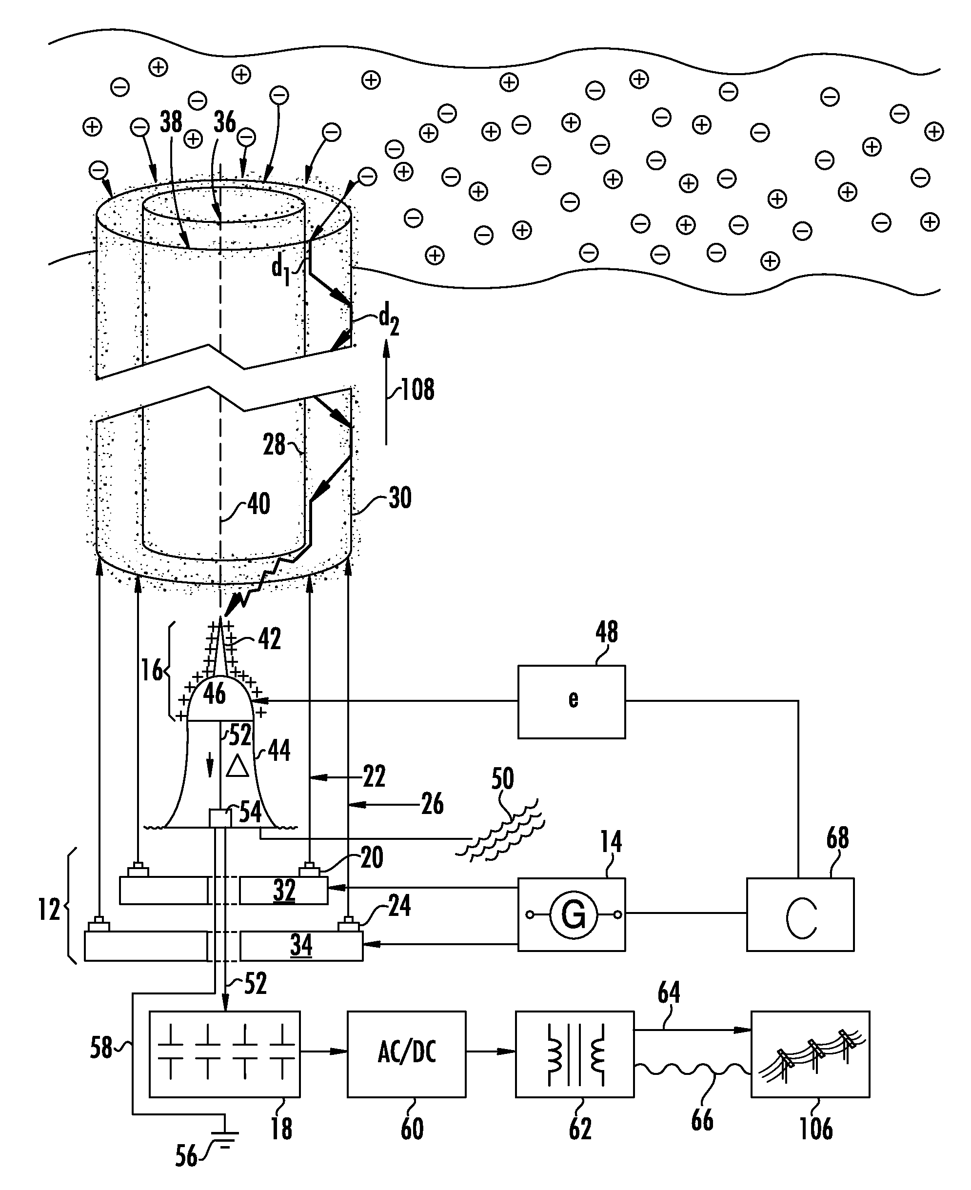
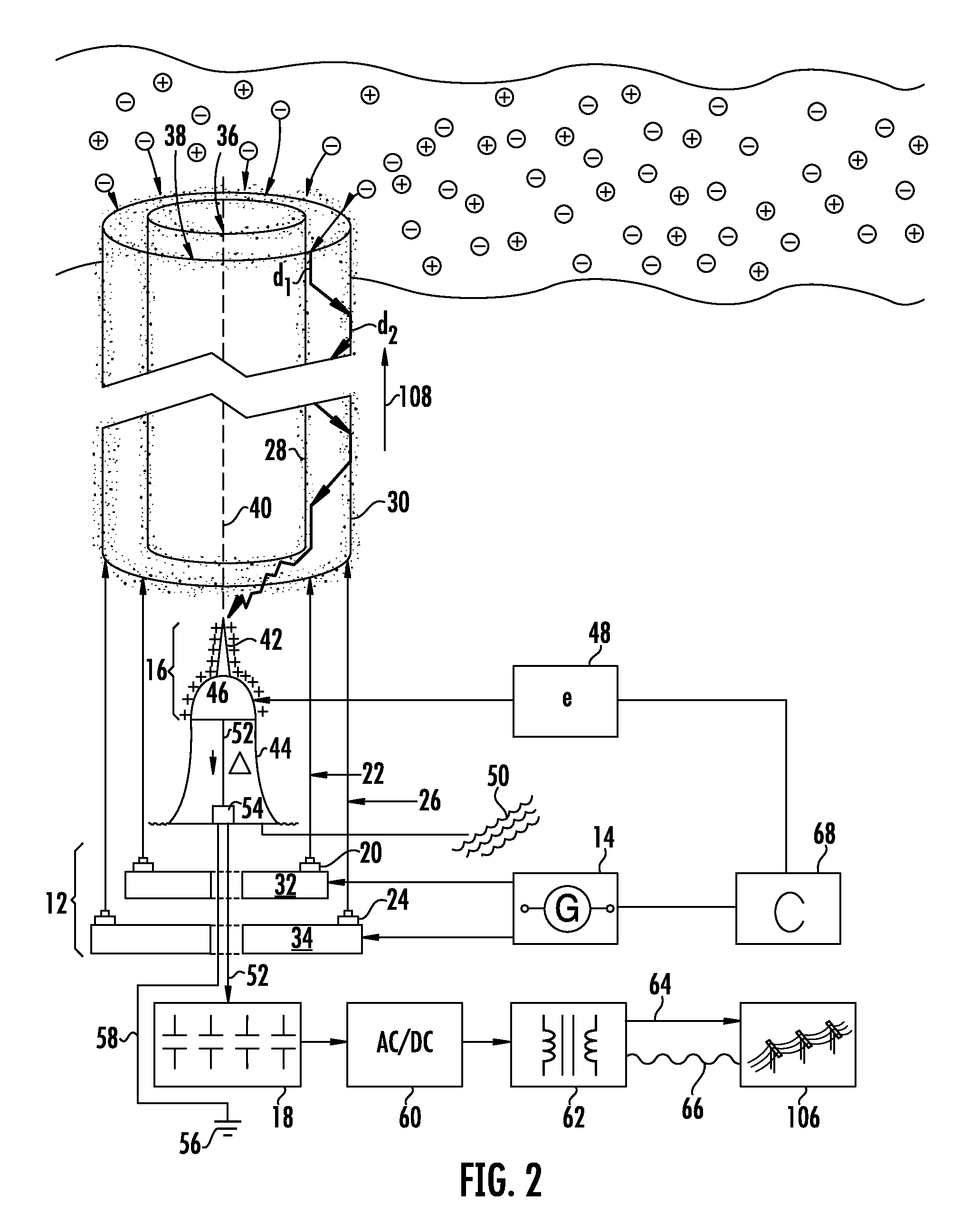
[0026]Referring to FIG. 2, apparatus 10 is comprised of three primary components: 1) a wireless conductive channel producing means 12 or “atmospheric auger” connected to an energy source 14, 2) charged particle receiving means 16 and 3) energy storage means 18. Each primary component is described in detail below, together with secondary components of the subject apparatus.

[0027]Wireless conductive channel producing means 12 (hereinafter “plasma channel producing means”) is comprised of first ionizing beam emitting means 20 used to create a first ionizing beam 22, and second ionizing beam emi...


PUM


Abstract

A charged particle induction apparatus and method comprising a high power light emitting means, such as a laser array, in operable communication with a high energy output means to accomplish initiation of at least two concentric plasma channels in atmosphere extending from the Earth's surface to the charge-rich upper atmosphere, including the ionosphere, for the transmission of charged particles therethrough to ground using the surrounding atmosphere as an insulator. The transmitted energy is drawn down (due to an artificially created potential) through the conductive plasma channels to collection means.

Description

RELATED APPLICATION[0001]This application claims the benefit of U.S. Provisional Application No. 61 / 280,131, filed Oct. 31, 2009 and entitled, System, Method and Apparatus For Inducing The Flow of Charged Particles From The Ionosphere to Ground Through Concentric Laser Induced Plasma Channels.FIELD OF THE INVENTION[0002]The present invention relates to the transmission of ionospheric energy through at least two “ionosphere-to-ground” coaxial laser-induced plasma channels formed through the Earth's atmosphere. As used herein, the term “ionosphereric energy” means charged particles, namely ions and electrons, in the ionosphere. As used herein, the term “channel” means a conduit having walls comprised of ionized or partially ionized gas, the channel being substantially ring-shaped in cross-section, the walls serving as the conductive path through which charged particles are induced to ground.BACKGROUND OF THE INVENTION[0003]The need to develop alternative clean renewable energy supplie...

Claims


Application Information

Patent Timeline
Patent Type & Authority Patents(United States)
IPC IPC(8): H01T23/00
CPCH02N99/00H05F7/00
Inventor LANE, GLENN
Owner GLENN LANE FAMILY LIMITED LIABILITY
Why Eureka
Try Eureka