Sandpaper with non-slip coating layer and method of using

a technology of non-slip coating and sandpaper, which is applied in the field of sandpaper with non-slip coating layer and method of use, can solve the problems of difficult to grasp, hold, and maneuver conventional sandpaper, difficult to grasp, and achieve the effects of improving durability, improving flexibility, and being easy to use and comfortable to us

Active Publication Date: 2014-03-04
3M INNOVATIVE PROPERTIES CO
View PDF30 Cites 7 Cited by
  • Summary
  • Abstract
  • Description
  • Claims
  • Application Information

AI Technical Summary

Benefits of technology

[0010]The industry is always seeking improved abrasive articles, such as sandpaper, that are easier and more comfortable to use, more durable, easier and less expensive to produce, and have the desired performance attributes as abrasive articles. It would be desirable to provide sandpaper that has a non-slip surface that provides improved handling, and is therefore easy and comfortable to use, is easy and inexpensive to make, has improved cut, has improved durability, and produces finer scratches than a comparable sheet of sandpaper.
[0015]In another aspect, the non-slip coating layer, when bonded to itself, may have an adhesive strength that is less than the two-bond adhesive strength (i.e. the adhesive strength of the non-slip coating layer to the backing layer), such that the non-slip coating layer does not separate from the backing layer when the non-slip coating layer is separated from itself. In another aspect, the non-slip coating layer, when bonded to itself, may have an adhesion level that is less than the cohesive strength of the non-slip coating layer, such that the non-slip coating layer is not damaged when the non-slip coating layer is separated from itself.
[0021]In yet another aspect, the present invention provides a method of making a sheet of sandpaper having a non-slip coating layer by hot melt coating, comprising the steps of providing a paper backing layer having opposed first and second major surfaces, coating an adhesive make coat on the first major surface, at least partially embedding abrasive particles in the make coat, thereby forming an abrasive surface, providing a liquid hot melt pressure sensitive adhesive, coating the hot melt pressure sensitive adhesive on the second major surface, and curing (for example, using UV radiation) the hot melt pressure sensitive adhesive, thereby reducing the level of tack of the hot melt pressure sensitive adhesive to the desired level to form the non-slip coating layer.
[0022]In a specific embodiment, the present invention provides a sheet of sandpaper for hand sanding a work surface comprising a paper backing layer having opposed first and second major surfaces, an adhesive make coat on the backing layer first major surface, abrasive particles at least partially embedded in the adhesive make coat, thereby defining an abrasive surface, and a non-slip coating layer on the backing layer second major surface consisting essentially of an acrylic polymer coating having a low level of tackiness, wherein the non-slip coating layer has a thickness of no greater than about 2 mils.
[0025]Advantages of certain embodiments of the present invention include providing sandpaper having a non-slip coating layer that makes the sandpaper easier and more comfortable to use than conventional sandpaper. In addition, making the non-slip coating layer is relatively simple and inexpensive, and does not otherwise affect the desirable performance attributes of the abrasive article. Additional advantages may include improved durability, improved flexibility, improved moisture resistance, and improved grip and hand appeal during use.

Problems solved by technology

Sanding by hand can, of course, be an arduous task.
The thin, flat, slippery nature of conventional sandpaper backing materials makes conventional sandpaper difficult to grasp, hold, and maneuver.
Holding the sandpaper in this manner is uncomfortable, can lead to muscle cramps and fatigue, and is difficult to maintain for an extended period of time.
In addition, the thumb is typically in contact with the abrasive surface of the sandpaper, which can irritate or damage the skin.
Also, because the thumb is positioned between the sandpaper and the work surface, grasping the sandpaper in this manner also interferes with the sanding operation.
Because the lifted portion is not in contact with the work surface, the full sanding surface of the sandpaper is not utilized, and the effectiveness of the sandpaper is, therefore, diminished.
This, in turn, causes the sandpaper to wear and / or load unevenly, and produces an uneven sanding pattern on the work surface.
Folding the sandpaper, however, produces a jagged edge, and also weakens the sandpaper along the fold line.
During the rigors of sanding, the weakened fold line may tear, thereby resulting in premature failure of the sandpaper.

Method used


Image

  • Sandpaper with non-slip coating layer and method of using
  • Sandpaper with non-slip coating layer and method of using

Examples


examples

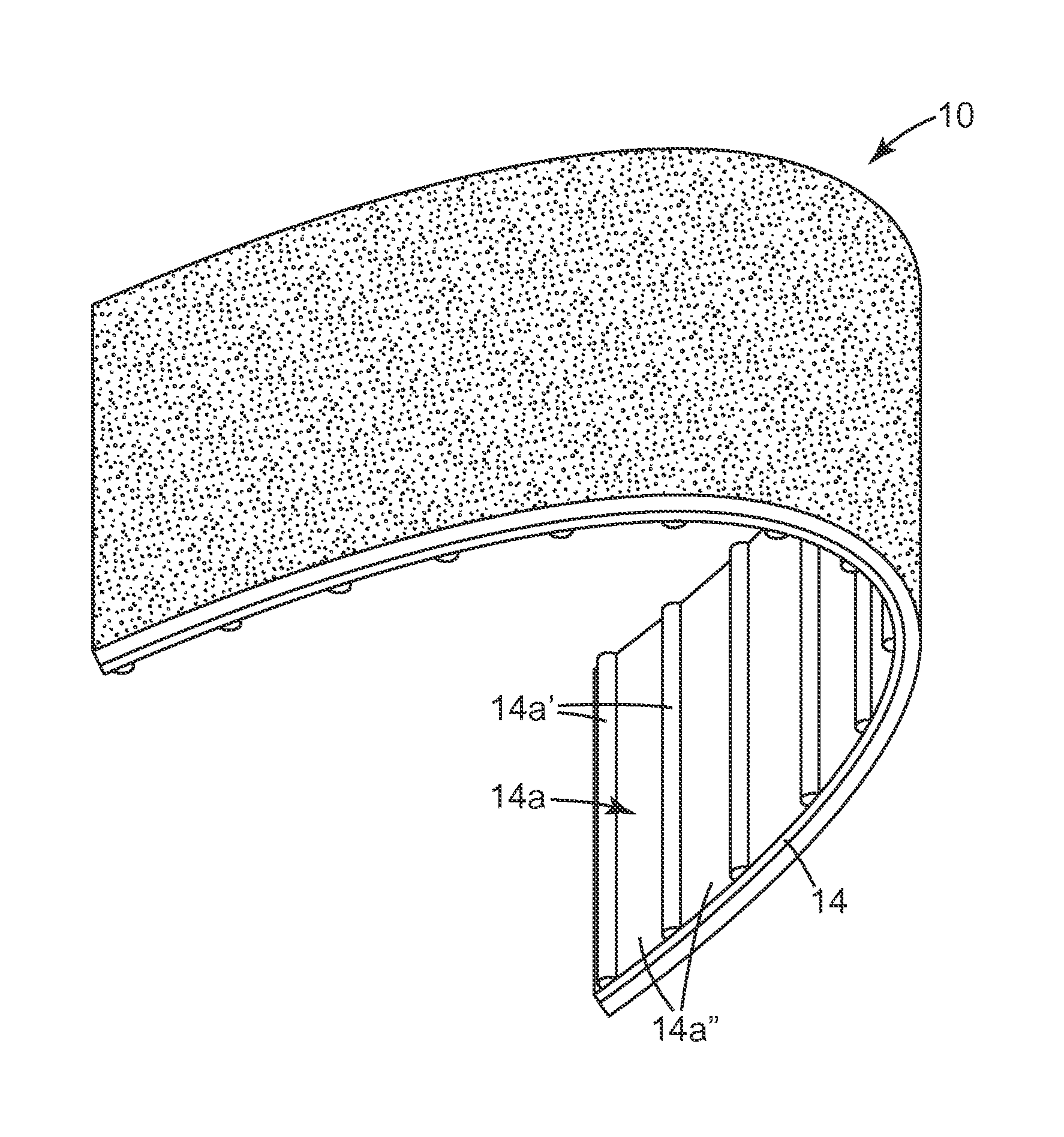
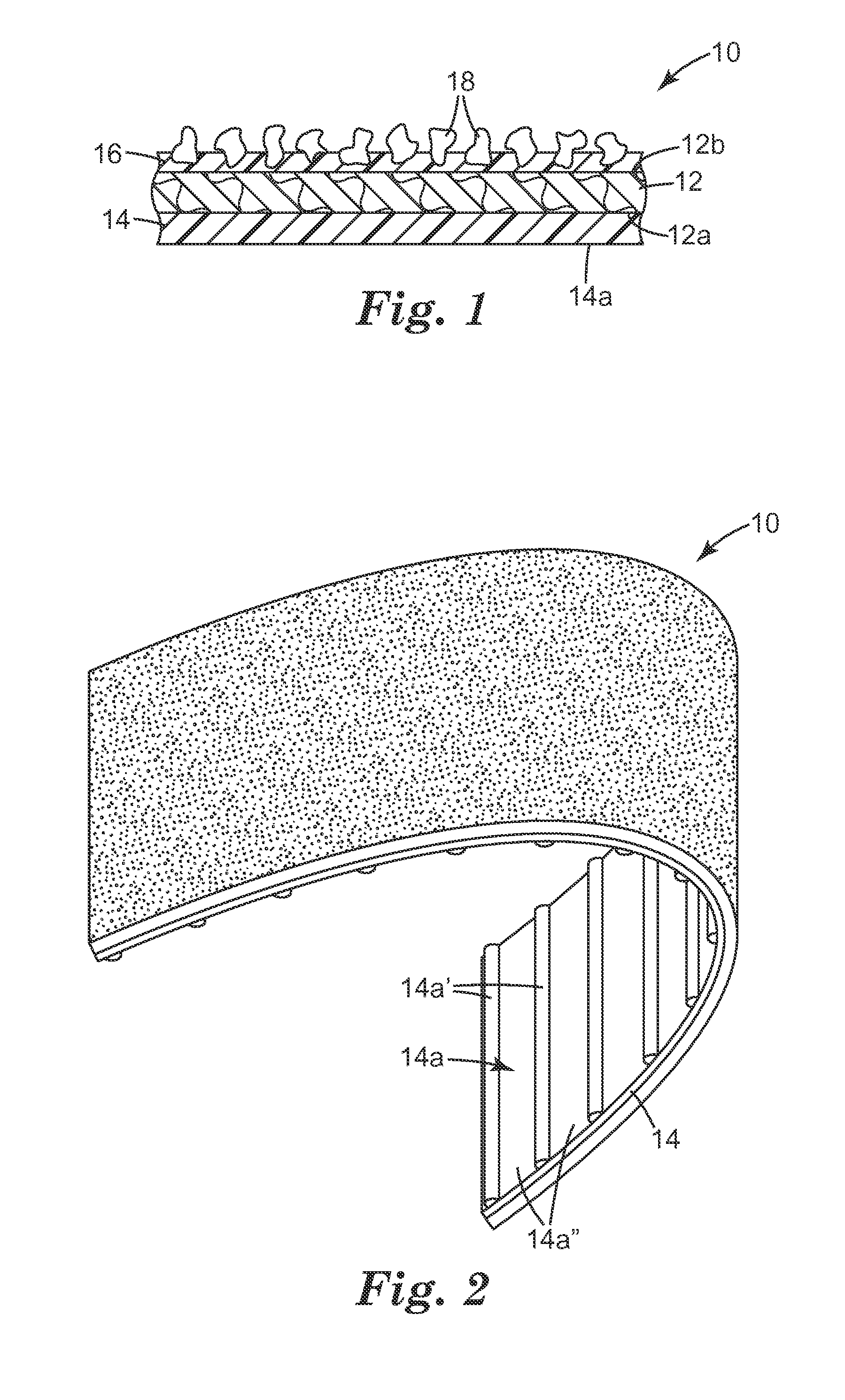
[0080]In each of the Examples set forth below, commercially available sandpaper sold by 3M Company, St. Paul, Minn., under the product designation “216U P150 Production RN Paper A Weight, Open Coat, Fre-Cut” was used to make an abrasive article 10 having the construction shown in FIG. 1. 216U sandpaper is a general purpose sandpaper having an A-weight paper backing, a phenolic resin coated on one side, and aluminum oxide abrasive particles at least partially embedded in the phenolic resin. The second side (i.e. the non-abrasive side opposite the abrasive surface) of the sandpaper was then coated with one of the non-slip coating layers described below.

[0081]For each of Examples 1-8, the resulting non-slip coating layer 14 had a low level of tack that allowed the non-slip coating layer 14 to be folded over onto itself, and allowed the contacting surfaces to be readily separated without damaging either of the non-slip coating layer 14 surfaces, and without damaging or separating from t...

example 1

[0085]Example 1 was 216U sandpaper wherein the second side was coated with a blend of 90% by weight Kraton D-1161K SIS block copolymer sold by Kraton Polymers, LLC of Houston, Tex., and 10% by weight Wingtack Plus tackifier sold by Sartomer Company Inc. of Exton, Pa., dissolved in toluene, such that the resulting solution was about 40% by weight solids. The blend was coated onto the backing layer 12 to a thickness of 1.5 mils using a knife coater, and was allowed to dry at ambient conditions to allow the toluene to completely evaporate. The average coefficient of friction for Example 1 was not measured and is, therefore, not included in Table 1.

example 2

[0086]Example 2 was 216U sandpaper wherein the second side was coated with an acrylic hot melt adhesive produced by first partially polymerizing a liquid monomer mixture in an ethylene-vinyl acetate (EVA) pouch by exposing it to UV light. The liquid monomer mixture included 14% by weight 2-ethyl hexyl acrylate, 42% by weight butyl acrylate, 44% by weight methyl acrylate, and further included the following additives (in parts per hundred additives—ppha): 0.17 ppha Irgacure 651 photo-initiator sold by Ciba-Geigy Corporation of Hawthorne, N.Y., 0.06 ppha isooctyl thioglycolate, 0.004 ppha hexanediol diacrylate, 0.092 ppha alphabenzophenone, and 0.4 ppha Irganox 1076 antioxidant sold by Ciba Specialty Chemicals Corporation of Tarrytown, N.Y. The partially polymerized monomer mixture was then blended with the EVA pouch using a twin screw extruder, such that the partially polymerized monomer mixture blend also included 4 ppha ethylene-vinyl acetate (EVA). The partially polymerized pressur...


PUM

PropertyMeasurementUnit
glass transition temperatureaaaaaaaaaa
speedaaaaaaaaaa
thicknessaaaaaaaaaa

Abstract

A sheet of sandpaper includes a backing layer having opposed first and second major surfaces, an adhesive make coat on the first major surface, abrasive particles at least partially embedded in the make coat, thereby defining an abrasive surface, and a non-slip coating layer on the second major surface. Methods of making and using such sandpaper are also provided.

Description

CROSS REFERENCE TO RELATED APPLICATION[0001]This application claims the benefit of U.S. Provisional Patent Application No. 61 / 076,821, filed Jun. 30, 2008, the disclosure of which is incorporated by reference herein in its entirety.BACKGROUND[0002]The present invention relates generally to abrasive articles for abrading a work surface such as, for example, flexible sheet-like abrasive articles.[0003]Sheet-like abrasive articles are commonly used in a variety of sanding operations including, for example, hand sanding of wooden surfaces. In hand sanding, the user holds the abrasive article directly in his or her hand and moves the abrasive article across the work surface. Sanding by hand can, of course, be an arduous task.[0004]Sheet-like abrasive articles include, for example, conventional sandpaper. Conventional sandpaper is typically produced by affixing abrasive material to a relatively thin, generally non-extensible, non-resilient, non-porous backing (e.g., paper). The thin, flat...

Claims


Application Information

Patent Timeline
Patent Type & Authority Patents(United States)
IPC IPC(8): B24D11/00
CPCB24D11/02B24B37/22B24B37/245B24D11/001
Inventor PETERSEN, JOHN, G.
Owner 3M INNOVATIVE PROPERTIES CO
Why Eureka
Try Eureka