
Hot-trap assembly for trapping unreacted gas by-products

a technology of unreacted gas and hot-trap assembly, which is applied in the field of hot-traps, can solve the problems of reducing the production cycle time and/or the need for frequent cleaning cycles, affecting the process efficiency, and affecting the efficiency of the process, so as to achieve convenient, efficient and cost-effective removal

Inactive Publication Date: 2013-08-20
OERLIKON SOLAR AG (TRUEBBACH)
View PDF7 Cites 4 Cited by
  • Summary
  • Abstract
  • Description
  • Claims
  • Application Information

AI Technical Summary

Benefits of technology

The invention is a device that can remove reaction by-products and unreacted reagents from exhaust gases. It is designed to provide ideal conditions for cleaning the exhaust gas by offering a simple and cost-effective solution.

Problems solved by technology

However, the reaction by-products and / or unreacted reagents tend to aggregate together under conditions prevalent in the module exhaust, the vacuum pump and the equipment piping, which may lead to negative effects on the process efficiency, blockage of the piping and vacuum pumps, reduction of production cycle time and / or the need for frequent cleaning cycles.
Especially, the vacuum pumps are affected since the pump increases the local pressure from process pressure up to atmospheric pressure and heats up the gas due to the compression.
Both effects result in lead to an increased reaction of the process gases inside the vacuum pump which may lead to metallic or oxidic deposition (e.g. Zn or ZnO from diethyl zinc) which, in turn, result in reduced lifetime of the pumps, a clogging of the vent lines etc.
This problem is even more pronounced during production in industrial scale, where high throughput of substrates requires a high consumption of process gases.
However, cold-traps will be saturated very fast and may lead to a concentration of a single component in the exhaust stream which might be a health hazard, requiring additional safe handling requirements.
Conventional hot-traps require extensive and frequent cleaning and / or replacement which, due to the construction of the hot-trap, requires a considerable amount of time.
This, in turn leads to a reduced uptime of the vacuum processing system and high maintenance costs.
Consequently, conventional hot-traps only provide sub-optimal reaction conditions.
Thus, conventional hot-traps do not offer ideal reaction conditions over their full length.

Method used


Image

  • Hot-trap assembly for trapping unreacted gas by-products
  • Hot-trap assembly for trapping unreacted gas by-products
  • Hot-trap assembly for trapping unreacted gas by-products

Examples


Embodiment Construction

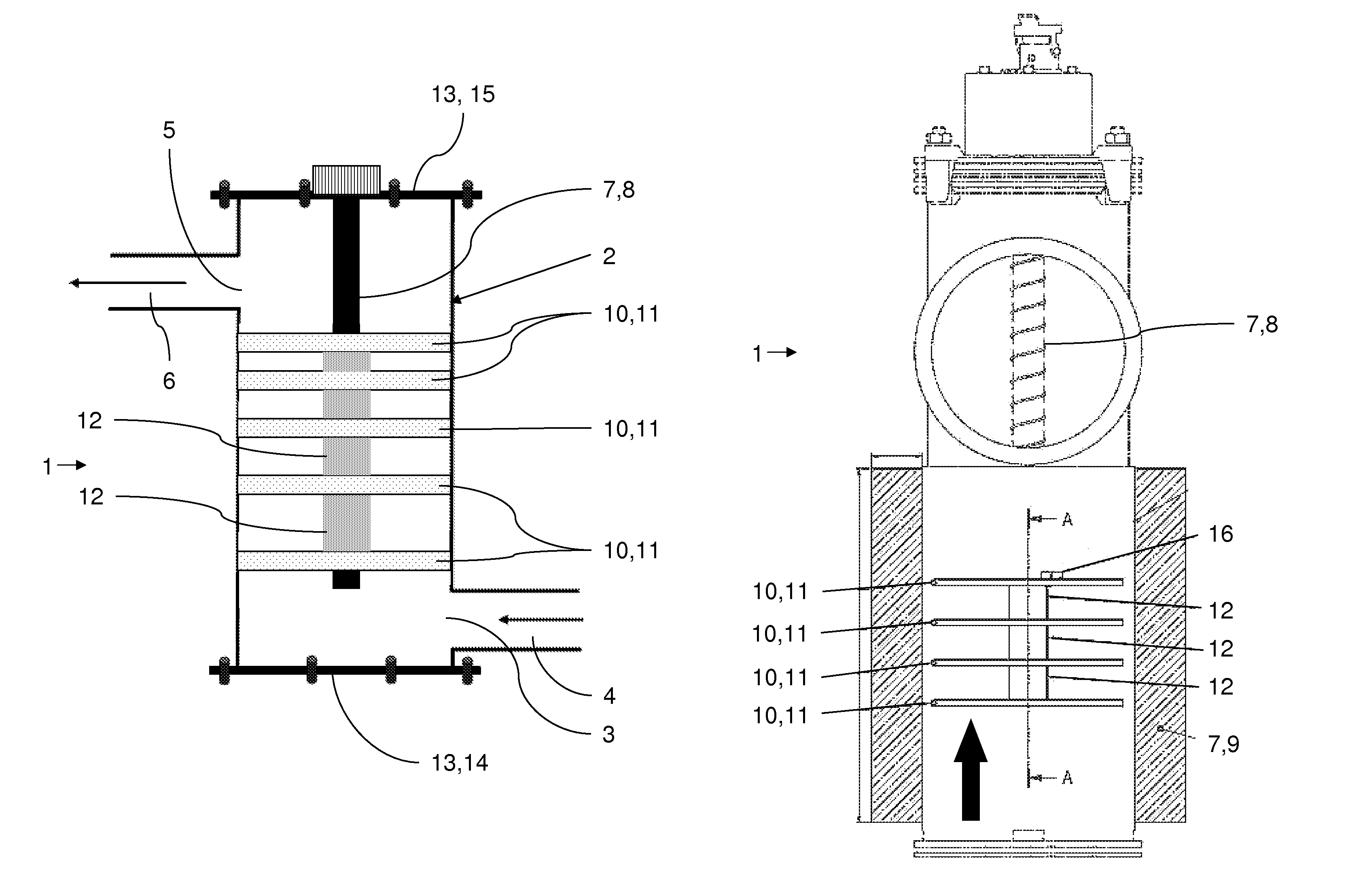
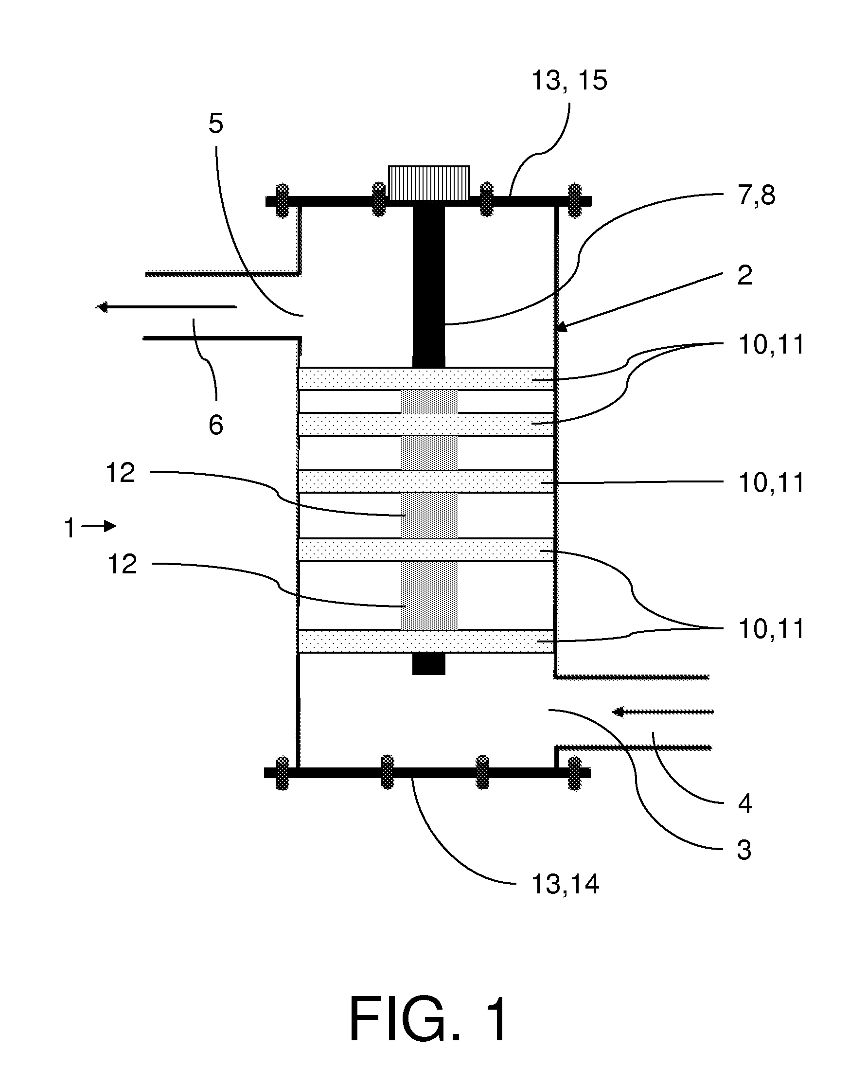
[0069]FIG. 1 shows a preferred embodiment of a hot-trap device 1 according to the invention. The hot-trap device comprises an enclosure 2 with the shape of a cylindrical pipe comprising an inlet 3 and an outlet 5. The inlet is connected to a ZnO-LPCVD processing module by means of a first piping 4, while the outlet is connected to a turbomolecular vacuum pump by a second piping 6.

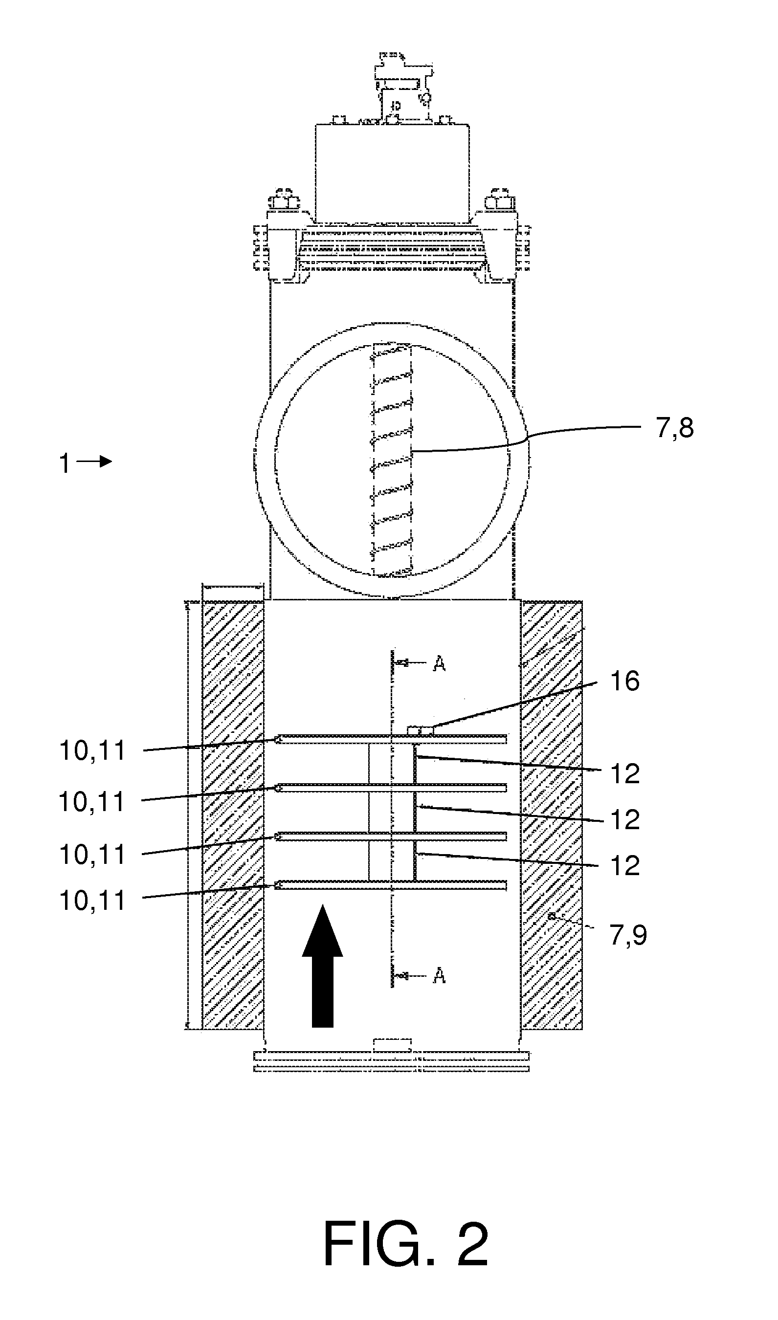
[0070]Furthermore, the hot-trap device comprises a heating means 7 that is an internal heating means implemented as an electrical heating rod 8 that is arranged in the center of the enclosure and extends over about the whole length of the enclosure. The heating rod is used to apply a temperature gradient within the hot-trap device, wherein the collector means closest to the inlet has a lower temperature that gradually increases to a higher temperature of the collector means closest to the outlet. Furthermore, the hot-trap device comprises a heating jacket as an outer heating means 9 (not shown in FIG. 1).

[0...


PUM

PropertyMeasurementUnit
temperaturesaaaaaaaaaa

Abstract

The present invention provides a hot-trap device (1) comprising an enclosure (2) with at least one inlet (3), at least one outlet (5) at least one heating means (7) and at least one collector means (10) for the conversion of reaction by-products into products, wherein the collector means is arranged within the enclosure between the inlet and the outlet has a diameter that substantially matches the diameter of the enclosure and has at least one opening (18).

Description

[0001]This is a National Phase Application filed under 35 U.S.C. 371 as a national stage of PCT / EP2009 / 057390, filed Jun. 15, 2009, and claiming the benefit under 35 U.S.C. 119(e) from U.S. Provisional Application No. 61 / 089,925, filed 19 Aug. 2008, Application No. 61 / 092,963, filed 29 Aug. 2008, and Application No. 61 / 099,340, filed 23 Sep. 2008, the content of each of which is hereby incorporated by reference in its entirety.TECHNICAL FIELD[0002]The present invention relates to the field of hot-traps, devices used in vacuum treatment systems to clean the gases exhausted from the treatment area. Particularly, the present invention discloses novel hot-trap devices comprising collector means for the efficient conversion of reaction by-products. This efficient conversion is inter alia achieved by the geometry, the spacing and the temperature of the collector means.BACKGROUND ART[0003]Vacuum processing systems are well known in the art and used for a variety of applications, e.g. for t...

Claims


Application Information

Patent Timeline
Patent Type & Authority Patents(United States)
IPC IPC(8): B01D45/00
CPCC23C16/4412
Inventor FISCHER, TOBIASSCHNEIDER, STEFANGOTTLICH, HAGENBHANGU, KAVREETVOGLER, BENJAMINWIDMEIER, CHRISTOPHZINDEL, ARNO
Owner OERLIKON SOLAR AG (TRUEBBACH)
Learn More