
Versatile system for a locking electro-thermal actuated MEMS switch

a technology of electro-thermal actuation and mems switch, which is applied in the field of micro-electromechanical system (mems) and wireless telecommunication technology, can solve problems such as restricting its further movement, and achieve the effects of convenient and fast adjustment, reliable device performance, and efficient process of providing single or multi-throw switches

Inactive Publication Date: 2010-05-11
SAMSUNG ELECTRONICS CO LTD
View PDF5 Cites 2 Cited by
  • Summary
  • Abstract
  • Description
  • Claims
  • Application Information

AI Technical Summary

Benefits of technology

The patent describes a system for reliably restricting movement of MEMS switch structures without relying on continuous electrostatic or electromagnetic forces. The system uses a lockable MEMS switch that is readily adaptable to various device applications and manufacturing processes. The system provides a clutch assembly that can be disposed in proximity to the switching member to prevent unintended movement. The system can be used in wireless communication devices to selectively couple the antenna input to one of multiple antenna structures. The technical effects of the patent include improved reliability, efficiency, and cost-effectiveness of MEMS switch devices.

Problems solved by technology

Once the switching member is in a desired position, the electrostatic or thermal expansion force may be removed from the clutch assembly, causing the engagement features to re-engage with the switching member, thereby restricting its further movement.

Method used


Image

  • Versatile system for a locking electro-thermal actuated MEMS switch
  • Versatile system for a locking electro-thermal actuated MEMS switch
  • Versatile system for a locking electro-thermal actuated MEMS switch

Examples


Embodiment Construction

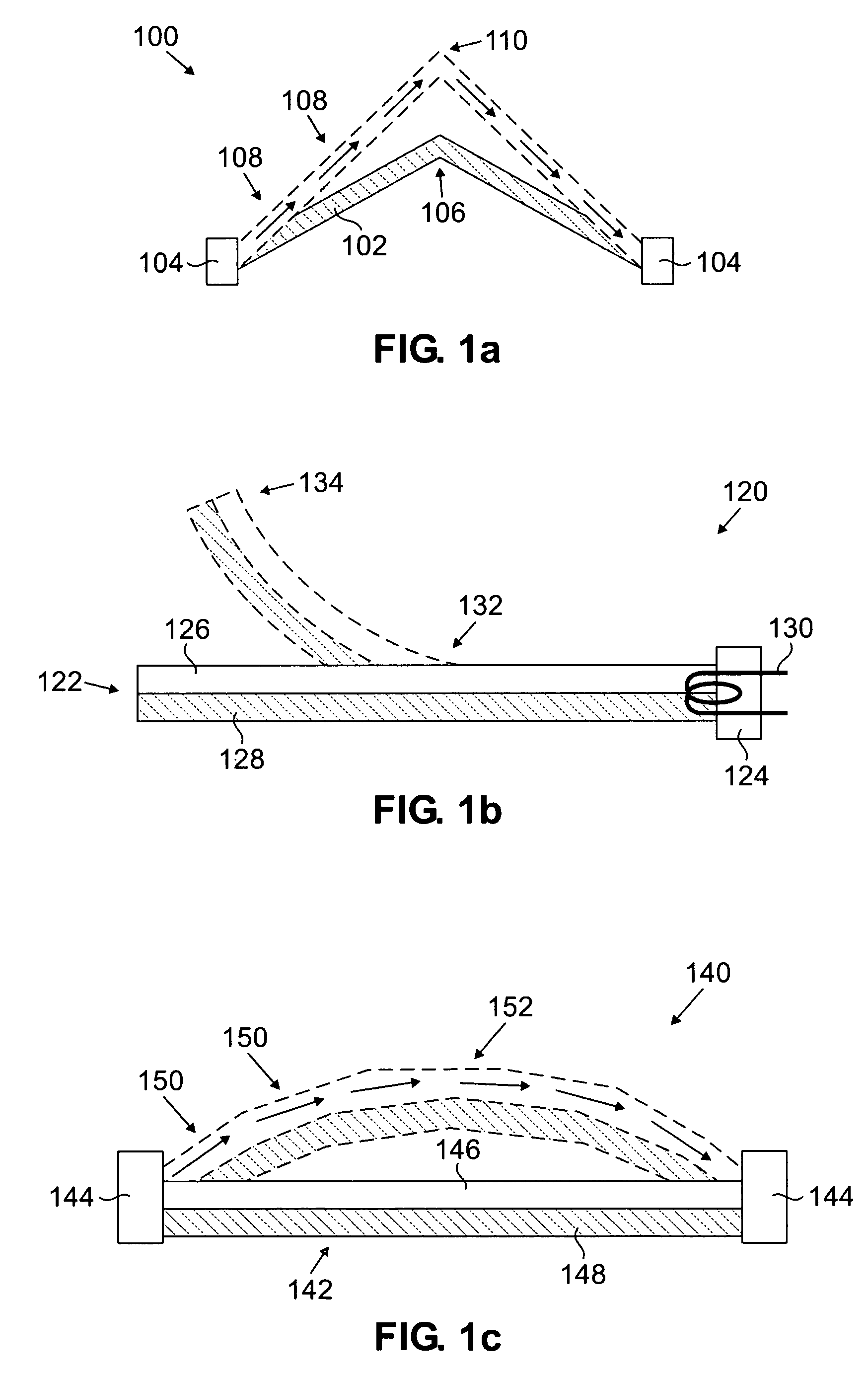
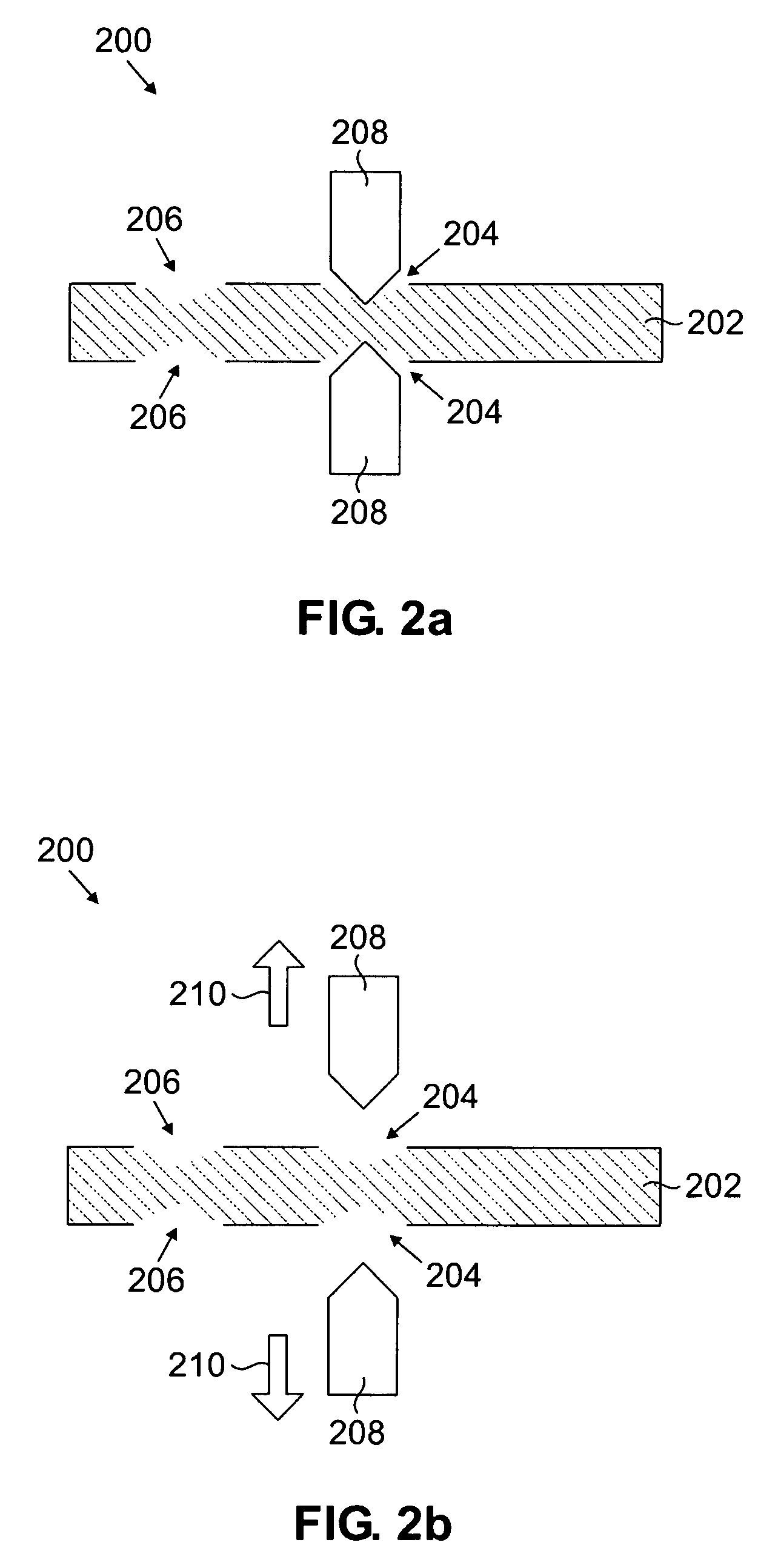
[0025]FIGS. 1 through 7, discussed below, and the various embodiments used to describe the principles of the present disclosure in this patent document are by way of illustration only and should not be construed in any way to limit the scope of the disclosure. Those skilled in the art will understand that the principles of the present disclosure may be implemented in any suitably arranged MEMS switching structure, or any other MEMS structure in which passive physical restriction of a movable component is desired.

[0026]The following disclosure provides a versatile system, comprising various architectures, apparatus and methods for reliable passive restriction of MEMS switching structures. The system is operable by electrostatic, electromagnetic or thermal expansion forces, but passively restricts MEMS switch structure movement in the absence of continuous electrostatic, electromagnetic or thermal expansion forces. The system is readily and easily adaptable to a number of device appli...


PUM


Abstract

A lockable MEMS switching architecture provided having a clutch assembly, a switching member, and an actuator. The clutch assembly has one or more engagement features located in proximity to the switching member—particularly one or more receiving features located upon the switching member. The clutch assembly is actuated to disengage the engagement features from the receiving features. The switching member is actuated to move in relation to the clutch assembly. Once the switching member is in a desired position, the clutch assembly is de-actuated, causing the engagement features to re-engage with the switching member, thereby restricting its further movement.

Description

CROSS-REFERENCE TO RELATED APPLICATION AND CLAIM OF PRIORITY[0001]The present application is related to U.S. Provisional Patent No. 60 / 668,522, filed Apr. 5, 2005, entitled “Electro-Thermal Actuated RF-MEMS Switch with Mechanical Latch”. U.S. Provisional Patent No. 60 / 668,522 is assigned to the assignee of the present application and is hereby incorporated by reference into the present disclosure as if fully set forth herein. The present application hereby claims priority under 35 U.S.C. §119(e) to U.S. Provisional Patent No. 60 / 668,522.TECHNICAL FIELD OF THE INVENTION[0002]The present application relates generally to the fields of micro-electromechanical systems (MEMS) and wireless telecommunication technologies, and more particularly, to a versatile system for passively restricting the movement of certain MEMS switch structures.BACKGROUND OF THE INVENTION[0003]The continual demand for enhanced speed, capacity and efficiency has resulted in dramatic advances in a variety of manufac...

Claims


Application Information

Patent Timeline
Patent Type & Authority Patents(United States)
IPC IPC(8): H01H61/00H02N10/00
CPCH01H61/02H01H61/04H01H2061/006H01H2001/0047
Inventor ZHU, XUBROBSTON, MICHAEL L.
Owner SAMSUNG ELECTRONICS CO LTD
Learn More