
Air sterilizing assembly

a technology of air sterilization and assembly, which is applied in the field of medical equipment, can solve the problems of affecting the quality of air sterilization, and requiring longer exposure periods, and achieves the effects of reducing the number of exposures

Active Publication Date: 2013-07-30
NAUCHNO PROIZVODSTVENNOE PREDPRIYATIE MELITTA LLC
View PDF16 Cites 11 Cited by
  • Summary
  • Abstract
  • Description
  • Claims
  • Application Information

AI Technical Summary

Benefits of technology

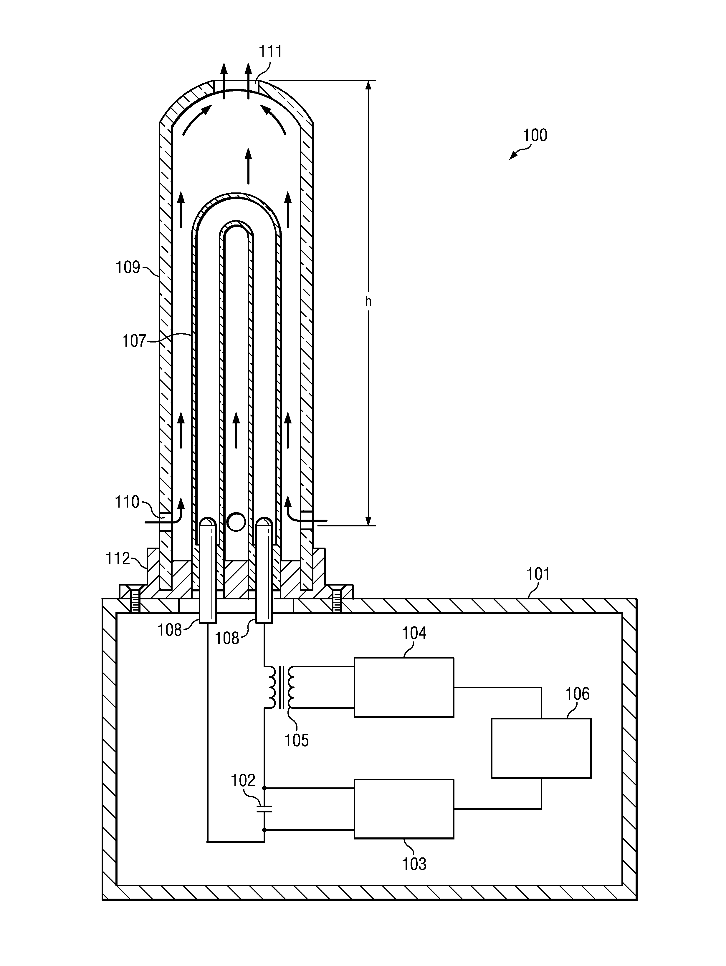
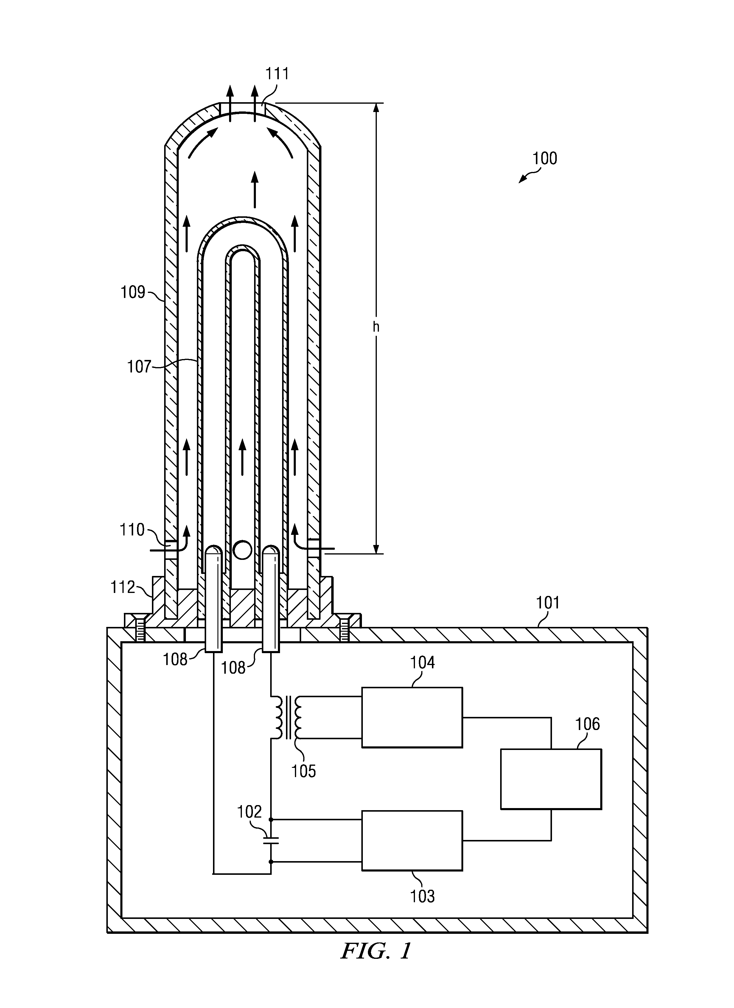
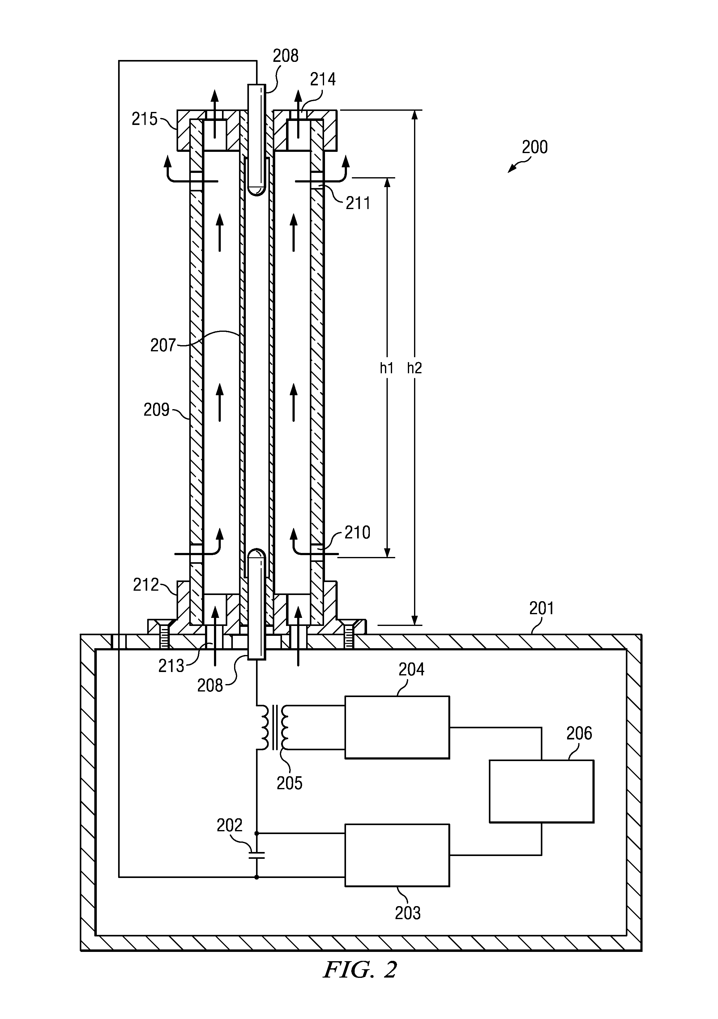
[0004]An aspect of the disclosed embodiments is aimed at simplifying the design of a device for improving the efficiency and quality of air disinfection or sterilization. An embodiment of the air disinfection device of the present disclosure may contain a body housing a power supply and control unit, which, in turn, includes an energy storage capacitor and a high-voltage constant current source. This device may also contain an ignition pulse generator, a ferrite-core pulse transformer, and a program control unit, together with an ultra-violet radiation source in the form of a pulsed gas-discharge lamp mounted on the body and enclosed in a tubular quartz casing. Given that the energy storage capacitor and the pulsed gas-discharge lamp may form a discharge circuit connected to the ignition pulse generator through the ferrite-core pulse transformer, the pulsed gas-discharge lamp may be placed in a bactericidal radiation translucent casing, with an option of convective air-cooling due to a natural draft inside the casing.
[0015]Providing a casing with orifices in the upper and lower levels may allow convection cooling of the pulsed gas-discharge lamp through ascending air flow, which passes through the casing as natural air draft. This may simplify the design of the source of ultra-violet radiation and the device as a whole. The aforementioned Ratio (1), which includes the power correlation coefficient and associated structural and power (operating) parameters of the unit, and which may be achieved through experimentation, may ensure that the range of A=(2 to 30)·1013 J2 / m5 s2 and will provide both optimal and efficient natural convection and cooling of the pulsed gas-discharge lamp, and ozone formation from oxygen in the air thanks to short-wave ultra-violet radiation and thermal disintegration of ozone due to heat emitted through pulsed electric discharges in the gas-discharge lamp. This may enable the device to function reliably and may ensure a high degree of air disinfection and a low level of ozone production in the processed premises.

Problems solved by technology

One disadvantage of these devices is low productivity, which is caused by low intensity monochromatic radiation that is emitted from the bactericidal lamps, and, as a result, contributes to needing longer exposure periods to ensure effective air disinfection.
The water cooling system used in a pulsed gas-discharge lamp complicates design, increases the weight of construction, and reduces the efficiency of air disinfection processes.

Method used


Image

  • Air sterilizing assembly
  • Air sterilizing assembly
  • Air sterilizing assembly

Examples


example 1

[0046]An air disinfection device 100 having 1 kW of power with a U-shaped pulsed gas-discharge lamp 107, positioned vertically, as shown in FIG. 1, in a quartz casing 9 that is 50 mm in diameter has the following technical parameters:[0047]C=100 μF=10−4 F, U0=2,800 V, F=2.5 Hz, h=0.275 m, Supper=2·10−4 m2, Slower=1.7·10−4 m2.

[0048]The device 100 may be installed in the room of following dimensions: length of 3.70 m, width of 3.05 meters, height of 3.85 m, with a total surface area of the room of 29.2 m3. Previously conducted microbiological tests with the disinfection device of these parameters showed that the device should work for 36 seconds in order to maintain efficient bactericidal air disinfection at 99.9% (i.e., 999 from every 1,0000 microorganisms are destroyed) in the room, measured for the Staphylococcus Aureus sanitary-indicative microorganism. The device was switched on by means of the program control unit 106 at the designated time, then the ozone level in the air was d...

example 2

[0049]An air disinfection device 300 having 200 W of power with a pulsed gas-discharge lamp 307 in the form of a straight cylinder, positioned horizontally, as shown in FIG. 3, in a quartz casing 309 that is 20 mm in diameter has the following technical parameters:[0050]C=60 μF=6·10−5 F, U0=1,400 V, F=3.3 Hz, h=20 mm=0.02 m, Supper=1 cm2=1·10−4 m2, Slower=1 cm2=1·10−4 m2.

[0051]The device 300 may be installed in the same room with a total surface area of 29.2 m3. According to microbiological tests to maintain efficient bactericidal air disinfection at 99.9%, measured for the Staphylococcus Aureus sanitary-indicative microorganism, this device should work for 300 seconds in order to achieve maximum results. The device was switched on by means of the program control unit 306 at the designated time, then, the average volume of ozone concentration in the air was calculated, which, in this case, was equal to 84 μg / m3. The received value would also not exceed the MAC of ozone permitted in ...


PUM


Abstract

An air disinfection device aimed at improving the efficiency and quality of air disinfection or sterilization may be achieved through an air disinfection device comprising a body housing a power supply and control unit, which, in turn, comprises an energy storage capacitor, a high-voltage constant current source, an ignition pulse generator, a ferrite-core pulse transformer, and a program control unit. The air disinfection device may also comprise an ultra-violet radiation source in the form of a pulsed gas-discharge lamp mounted on the body and enclosed in a tubular quartz casing. Given that the energy storage capacitor and the pulsed gas-discharge lamp may form a discharge circuit connected to the ignition pulse generator through the ferrite-core pulse transformer, the pulsed gas-discharge lamp may be placed in a bactericidal radiation translucent casing, resulting in convection air-cooling due to a natural draft inside the casing that disinfects and sterilizes surrounding air.

Description

TECHNICAL FIELD[0001]The disclosed embodiments relate to medical equipment, and more specifically, to equipment that can be used to improve the efficiency of disinfecting or sterilizing air in various rooms used for different purposes.BACKGROUND OF THE INVENTION[0002]Air disinfection / sterilizing devices may include one or more sources of ultra-violet radiation in the form of mercury gas-discharge bactericidal lamps and operating in a continuous lighting mode (for example, RU 2153886 C1, A61L9 / 20, 2000; RU 2153886 C1, A61L9 / 20, 2007; or EP 0220050, A61L9 / 18, 1987). One disadvantage of these devices is low productivity, which is caused by low intensity monochromatic radiation that is emitted from the bactericidal lamps, and, as a result, contributes to needing longer exposure periods to ensure effective air disinfection.[0003]Another device used for air disinfection and deodorization contains a body housing a power supply and control unit, which, in turn, includes an energy storage ca...

Claims


Application Information

Patent Timeline
Patent Type & Authority Patents(United States)
IPC IPC(8): H01J17/34H01J17/28
CPCA61L9/20A61L2209/11A61L2202/25Y02A50/20
Inventor GOLDSHTEIN, YAKOV ABRAMMEROVICHSHASHKOVSKY, SERGEI GENNADEVICH
Owner NAUCHNO PROIZVODSTVENNOE PREDPRIYATIE MELITTA LLC
Learn More