Magneto-resistive effect element having spacer layer including main spacer layer containing gallium oxide and nonmagnetic layer
a technology of magnetoresistive effect and main spacer layer, which is applied in the field of magnetoresistive effect element configuration, can solve the problems of reducing the mr ratio, oxidizing the ferromagnetic layer, and the potential for a more prominent decrease in the mr ratio
- Summary
- Abstract
- Description
- Claims
- Application Information
AI Technical Summary
Benefits of technology
Problems solved by technology
Method used
Image
Examples
first embodiment
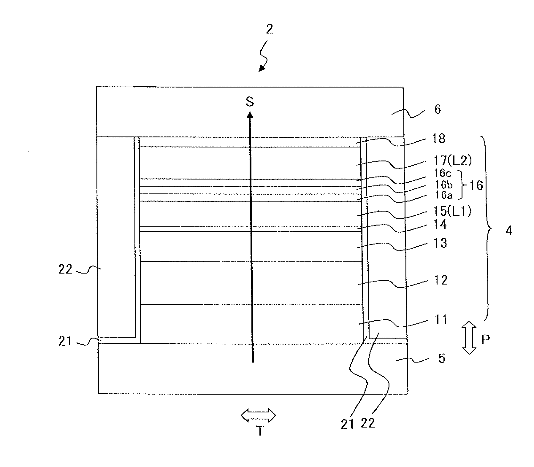
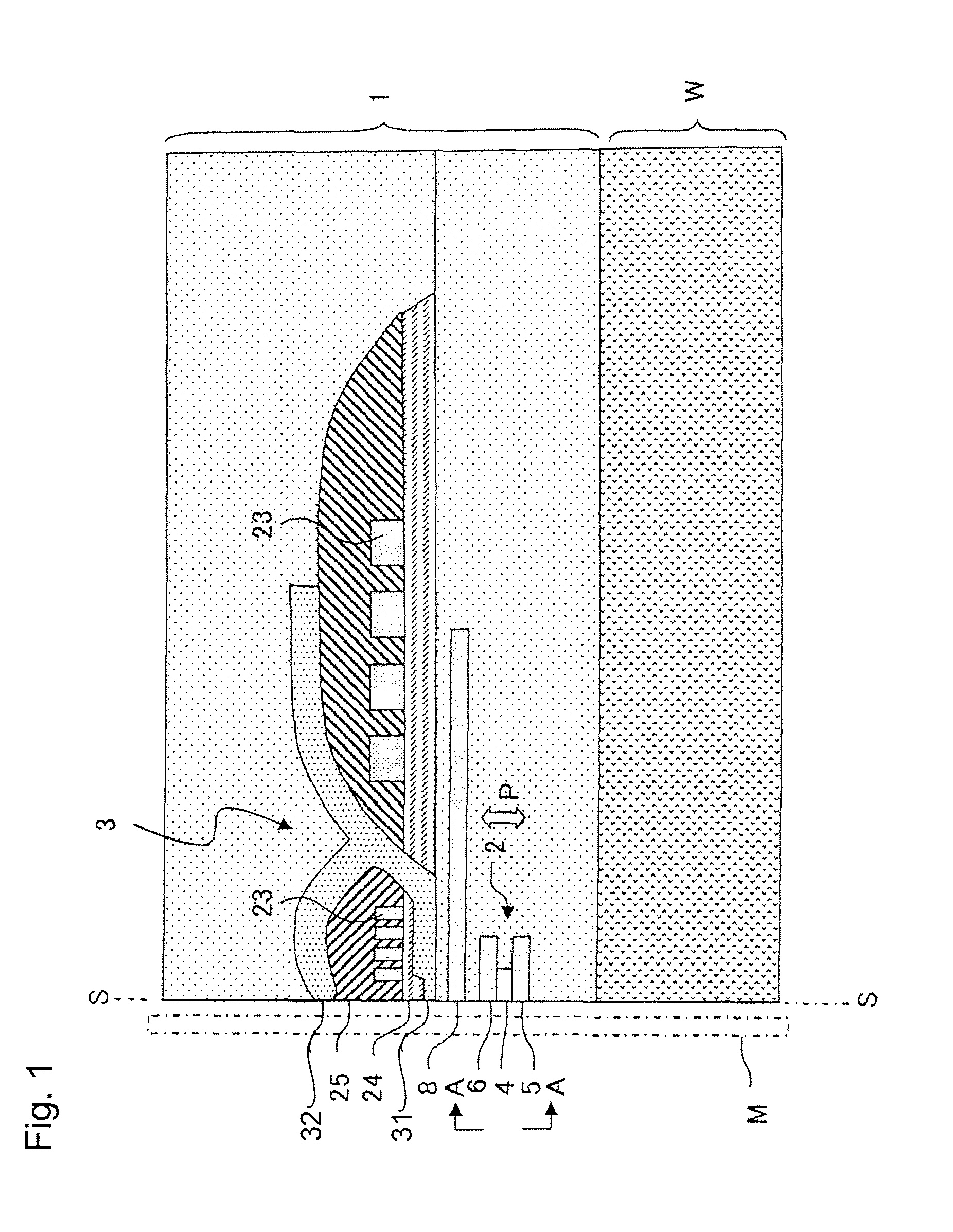
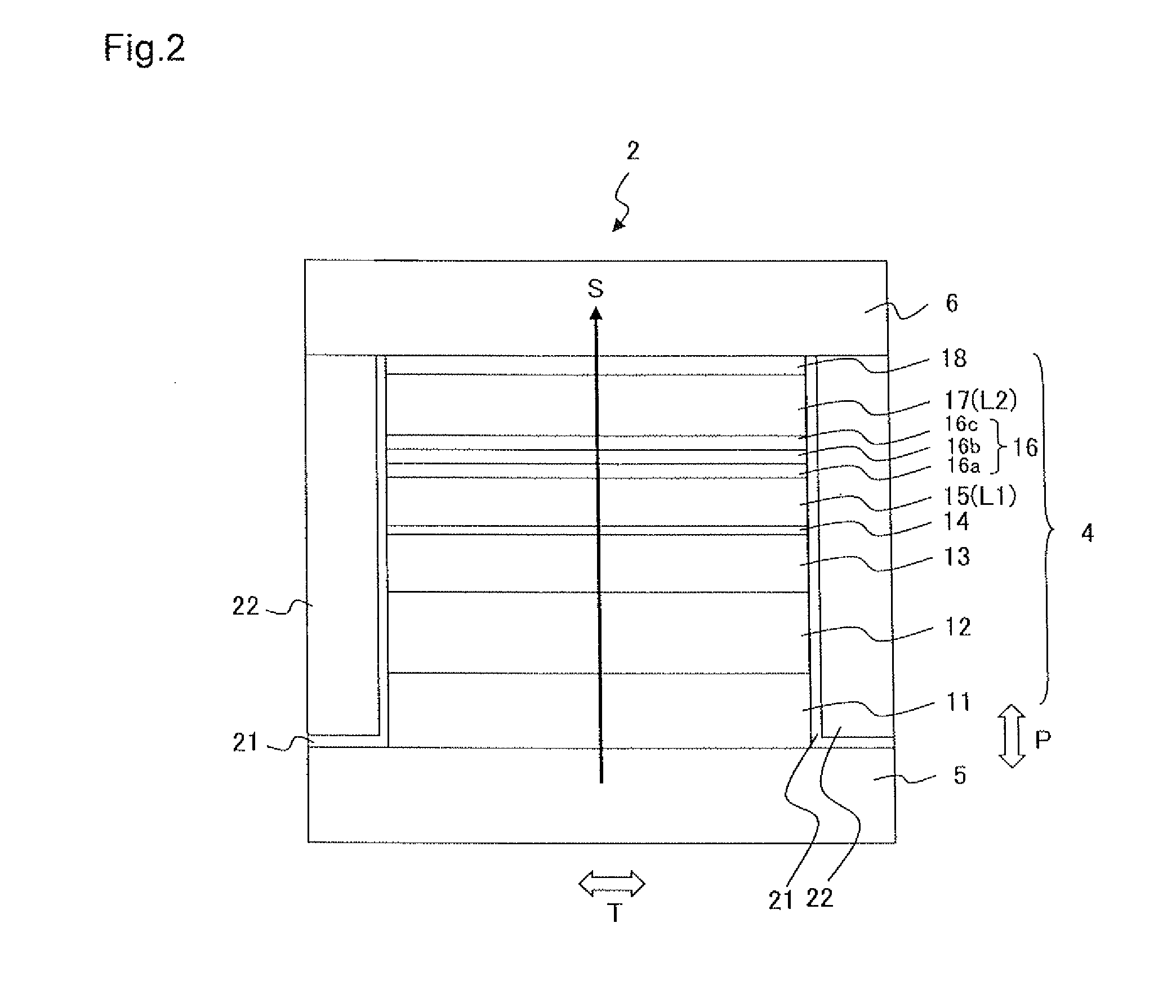
[0024]FIG. 1 illustrates a main part cross-sectional view of a thin film magnetic head 1 that relates to a first embodiment. The thin film magnetic head 1 is formed on a substrate W and includes a reproducing head 2 and a recording head 3. FIG. 2 is a side view of the reproducing head 2 as viewed from the A-A direction of FIG. 1 and illustrates the layer configuration of the reproducing head 2 on the air bearing surface S. The air bearing surface S is a surface of the thin film magnetic head 1 that opposes the recording medium M. An initial description will be given of the configuration of the reproducing head 2 with reference to FIG. 2.
[0025]The reproducing head 2 includes a spin valve type MR element 4, upper and lower shield layers 6 and 5 disposed so as to sandwich the MR element 4 in a film surface orthogonal direction (lamination direction) P, and bias magnetic field application layers 22 disposed on both sides of the MR element 4 in the track width direction T (paper surface ...
second embodiment
[0043]A thin film magnetic head 1 of the present embodiment is the same as the first embodiment indicated in FIG. 1 with the exception of the configuration of the reproducing head 2. The layer configuration of the MR element is indicated in FIG. 4 and Table 2. A reproducing head 102 includes an MR element 104 in which a plurality of layers are laminated in the same manner as in the first embodiment, and upper and lower shield layers 106 and 105 that are disposed so as to sandwich the MR element 104 in the film surface orthogonal direction P (lamination direction). The upper and lower shield layers 106 and 105 are also used as electrodes for the sense current S to flow sense current S in the film surface orthogonal direction P of the MR element 104.
[0044]With the present embodiment, a first magnetic layer L1 and a second magnetic layer L2 are respectively magnetization free layers 115 and 117 of which the magnetization directions changes in relation to the external magnetic field. Th...
example
[0055]The magnetoresistive effect film with the layer configuration indicated in Table 2 was formed on the substrate W made of Al2O3—TiC (ALTIC) using a radio frequency (RF) sputtering device. After film formation, heat treatment was performed for three hours at 250° C. The first and second magnetization free layers 115 and 117 are oriented in mutually orthogonal directions when there is no external magnetic field; however, they rotate freely when an external magnetic field is applied thereby generating a magnetoresistive effect.
[0056]The MR ratio was evaluated by changing the material and film thickness of the first nonmagnetic layer 116a in this multilayer film. Cu was used for the second nonmagnetic layer 116c. Table 4 illustrates MR ratios normalized by the MR ratio being set to 1 when a Ga40Cu60 alloy (film thickness 0.6 nm) is used as the first nonmagnetic layer 116a. The description of Ga x Cu (100-x) (when x is an integer between 0 and 100) indicates that the atomic percent ...
PUM
| Property | Measurement | Unit |
|---|---|---|
| thickness | aaaaa | aaaaa |
| thickness | aaaaa | aaaaa |
| mole fraction | aaaaa | aaaaa |
Abstract
Description
Claims
Application Information
 - R&D
- Intellectual Property
- Life Sciences
- Materials
- Tech Scout
- Unparalleled Data Quality
- Higher Quality Content
- 60% Fewer Hallucinations
Browse by: Latest US Patents, China's latest patents, Technical Efficacy Thesaurus, Application Domain, Technology Topic, Popular Technical Reports.
© 2025 PatSnap. All rights reserved.Legal|Privacy policy|Modern Slavery Act Transparency Statement|Sitemap|About US| Contact US: help@patsnap.com


