Degradation sensor

a technology of degradation sensor and conductivity, applied in the field of sensors, can solve problems such as loss of conductivity of the conducting member over its length, and achieve the effect of loss of conductivity

Inactive Publication Date: 2013-03-19
THE COMMONWEALTH OF AUSTRALIA - DEPT OF DEFENCE
View PDF3 Cites 2 Cited by
  • Summary
  • Abstract
  • Description
  • Claims
  • Application Information

AI Technical Summary

Problems solved by technology

Furthermore, corrosion of the structure or material may be accompanied by corrosion of the conducting member, depending on the material from which the conducting member is made, so changes in the conductivity or resistance may be indicative of corrosion (or other deterioration) in the structure or material.
Moreover, the conducting member may also corrode, ultimately leading to a loss of conductivity of the conducting member over its length.

Method used


Image

  • Degradation sensor
  • Degradation sensor
  • Degradation sensor

Examples


Embodiment Construction

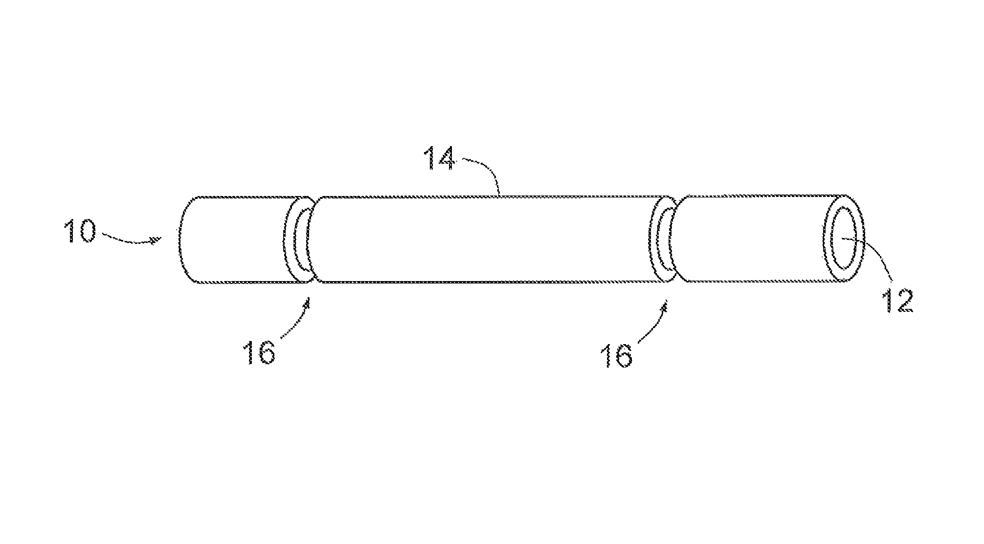
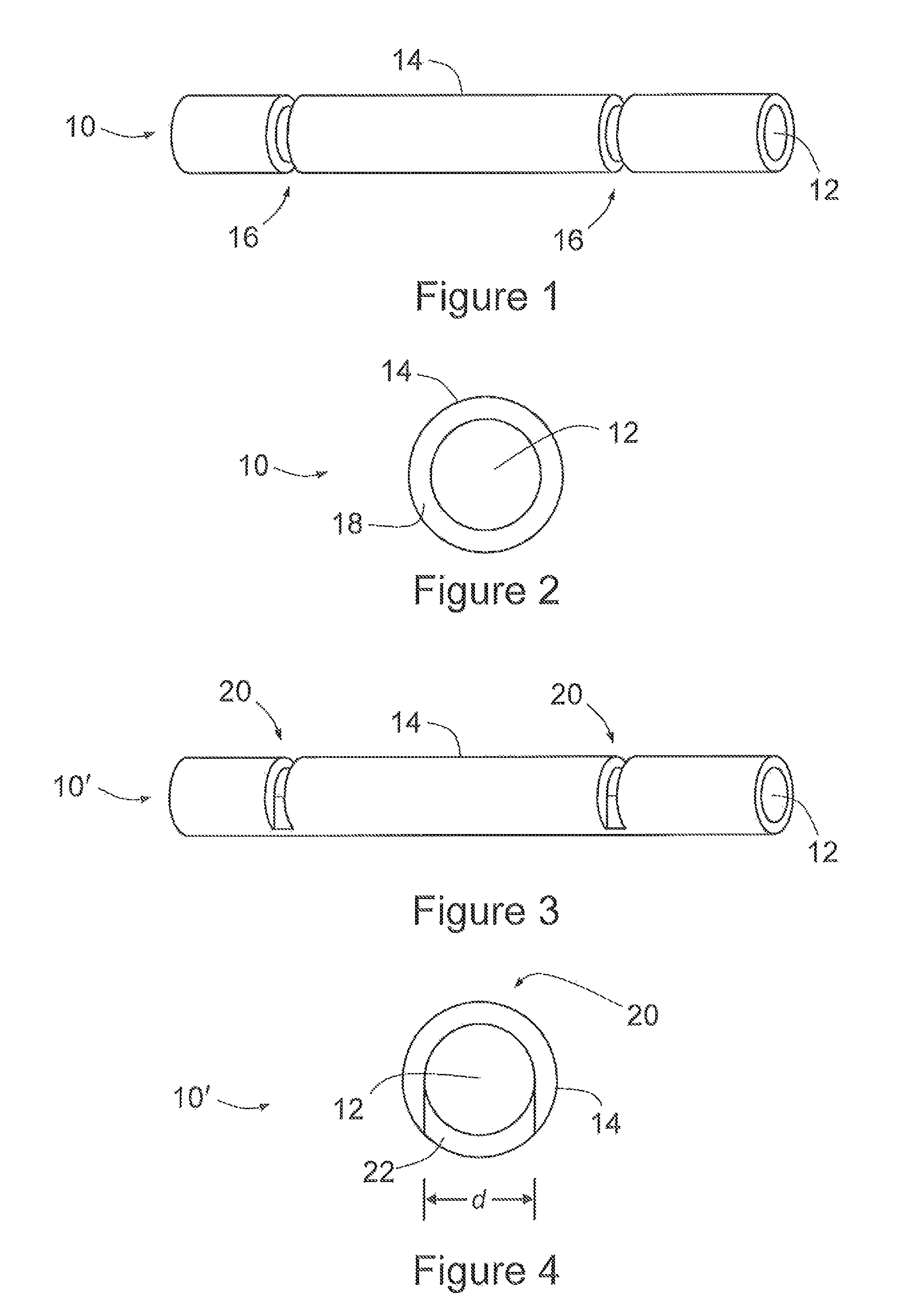
[0044]A sensor for detecting corrosion or other deterioration in typically metal surfaces, according to an embodiment of the present invention, is shown generally at 10 in FIG. 1. Sensor 10—formed from insulated wire (and hence also referred to as a ‘wire sensor’)—comprises a thin wire 12 of 25 μm to 200 μm diameter and, covering the wire, a thin insulating material 14, such as polyurethane or nylon, that is a few microns in thickness. Sensor 10 also has periodically spaced notches 16 where wire 12 is exposed, that is, there is no overlaying insulating material 14. Notches 16 are spaced 100 μm apart, though it will be appreciated that this spacing can be smaller or greater, including of the order of millimetres or more. Each notch 16 has a width—along the length of sensor 10—of 5 to 30 μm; in many applications a width at the smaller end of this range is preferable.

[0045]As will also be appreciated by those skilled in the art, sensor 10 may be of essentially any desired length, and m...


PUM


Abstract

A sensor for monitoring a structure or material. The sensor has a continuous elongate conducting member embedded in an insulating material and a conductivity or resistance meter. The insulating material has one or more gaps that expose the conducting member without allowing direct contact between the insulating material and the structure or material when the sensor is placed against the structure or material. The meter is arranged to monitor conductivity or resistance between the conducting member and the structure or material being monitored, and / or between two regions of the conducting member.

Description

RELATED APPLICATION[0001]This application is based on and claims the benefit of the filing date of AU application no. 2008900518 filed 5 Feb. 2008, the content of which as filed is incorporated herein by reference in its entirety.FIELD OF THE INVENTION[0002]The present invention relates to a sensor for monitoring a structure or material, to detect the effects of possible corrosion or other deterioration of structures (including buildings, vehicles, vessels or parts thereof) and materials.BACKGROUND OF THE INVENTION[0003]One existing method for detecting corrosion (disclosed in U.S. Pat. No. 6,805,788) employs electrochemical impedance spectroscopy. The conductivity of the monitored substrate is measured by locating a probe with a solid polymer electrolyte membrane that houses an electrode in contact with the surface of the substrate. Perturbations in an AC current or voltage across the monitored surface and the electrode are used to determine the impedance of the substrate. However,...

Claims


Application Information

Patent Timeline
Patent Type & Authority Patents(United States)
IPC IPC(8): G01R27/08
CPCG01N17/04
Inventor WILSON, ALAN RICHARD
Owner THE COMMONWEALTH OF AUSTRALIA - DEPT OF DEFENCE
Why Eureka
Try Eureka