Code sequence transmission method, wireless communication system, transmitter, and receiver

a transmission method and wireless communication technology, applied in multiplex communication, power management, high-level techniques, etc., can solve the problems of inability to use remaining power on data channels, inconvenient use, and inconvenient use, so as to improve system throughput and user throughput, improve power utilization efficiency, and improve system throughput

Active Publication Date: 2013-01-08
NEC CORP
View PDF26 Cites 0 Cited by
  • Summary
  • Abstract
  • Description
  • Claims
  • Application Information

AI Technical Summary

Benefits of technology

[0021]According to the present invention constituted as stated above, it is possible to improve the power utilization efficiency on the control channel and the data channel including a plurality of signals having different required qualities, and improve the system throughput and user throughput.
[0022]Namely, according to a first embodiment of the present invention, a bit sequence of a TFCI is transmitted repeatedly within one frame a plurality of times, a bit sequence of each TFCI is multiplied by one bit of a bit sequence of an SI, and a multiplication result is transmitted. It is thereby possible to transmit both the TFCI and the SCI without providing the signal field for the SI in the frame.
[0023]By doing so, even if the TFCI and SI differ in required quality, it is possible to satisfy the required qualities of both the TFCI and the SI and make a transmission power on each frame of an E-DPCCH (E-DCH Dedicated Physical Control channel) uniform.
[0024]Accordingly, the power utilization efficiency can be improved, the average power allocated to the E-DPDCH can be increased, and the system throughput and the user throughput can be improved.
[0025]Moreover, according to a second embodiment of the present invention, even if a control signal used only during soft handover is present, it is unnecessary to provide a signal field for the control signal. Therefore, even if the same frame format is always used, a deterioration in power utilization efficiency can be avoided and the throughput can be improved. Furthermore, since it is unnecessary to change the frame format according to whether the region is a soft handover region or the other region, procedures accompanying the change of the frame format can be reduced. In addition, control signal traffic on a wireless layer and in the network can be reduced.

Problems solved by technology

However, the conventional art has the following problems.
However, this power cannot be used for data transmission.
However, for the same reason as that stated above, this remaining power cannot be used on the data channel.
If the power that cannot be used for the data transmission is generated, then utilization efficiency for using resources of each mobile station is deteriorated, and an average transmission rate on the data channel is reduced.
As a result, system throughput and user throughput are deteriorated.
However, to change the format of the signal field, it is unfavorably necessary to take steps to do so in the base station and each of the mobile stations, and to increase the number of wireless layers and the number of control signals in the network.

Method used


Image

  • Code sequence transmission method, wireless communication system, transmitter, and receiver
  • Code sequence transmission method, wireless communication system, transmitter, and receiver
  • Code sequence transmission method, wireless communication system, transmitter, and receiver

Examples


first embodiment

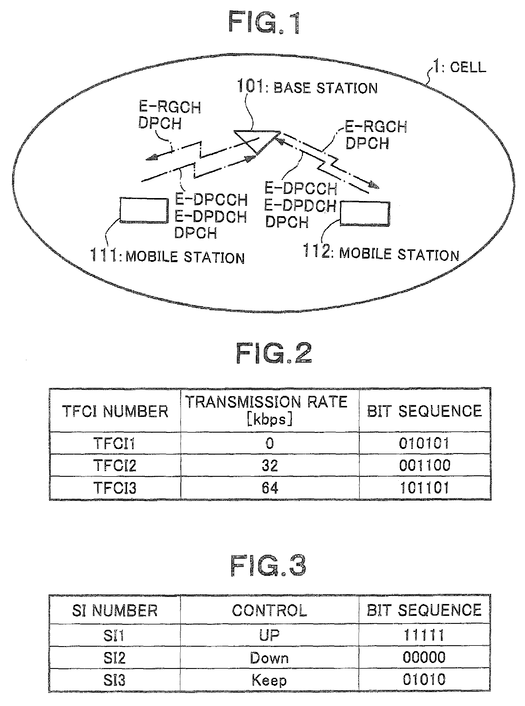
[0039]FIG. 1 is a block diagram of a wireless communication system according to a first embodiment of the present invention. In FIG. 1, the wireless communication system according to the first embodiment of the present invention includes a base station 101 provided in a cell 1, and mobile stations 111 and 112 connected to the base station 101. The following channels are configured between this base station 101 and the respective mobile stations 111 and 112, and data is transmitted on uplink (in a direction from the mobile stations 111 and 112 to the base station 101).

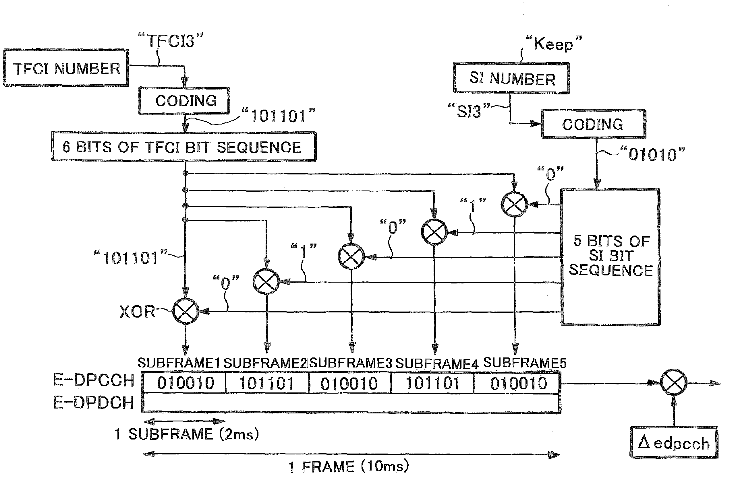
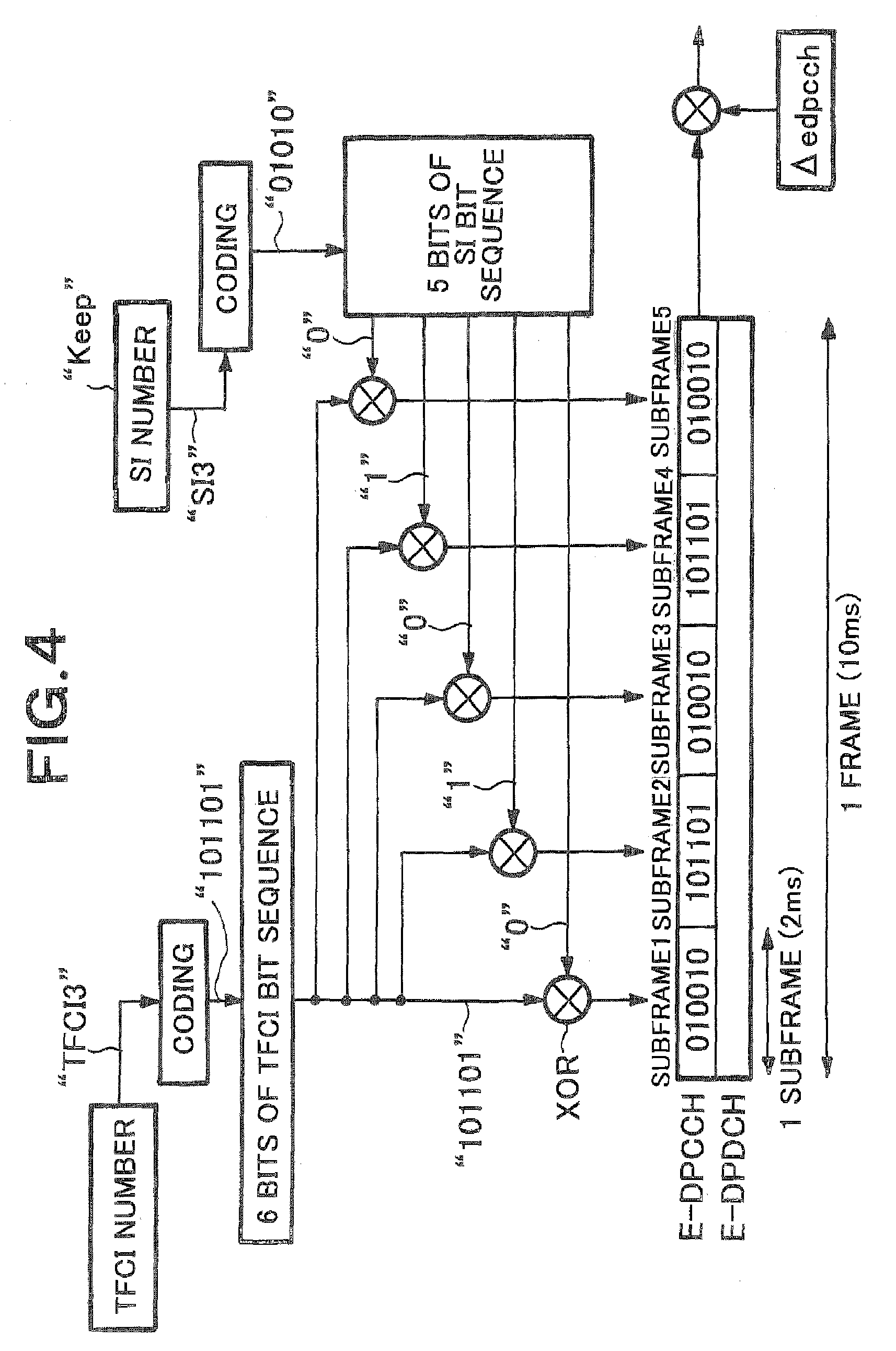
[0040]Referring to FIG. 1, E-DPCCH is an uplink channel for transmitting a control signal on an EUDCH, and E-DPDCH (E-DCH Dedicated Physical Data Channel) is an uplink channel for transmitting data on the EUDCH. In addition, E-RGCH (EDCH Relative Grant Channel) is a channel on downlink (in a direction from the base station 101 to the mobile stations 111 and 112) for transmitting the control signal on the EUDCH, and DPCH...

second embodiment

[0072]FIG. 8 is a block diagram of a wireless communication system according to a second embodiment of the present invention. Referring to FIG. 8, the wireless communication system according to the second embodiment of the present invention includes a base station 1001 provided in the cell 1, mobile stations 1011 and 1012 connected to the base station 1001, a base station 1002 provided in a cell 2, and the mobile stations 1012 connected to the base station 1002. Namely, the mobile station 1012 present near a boundary between the cells 1 and 2 establish radio links to the two base stations 1001 and 1002, respectively. Only the base station 1001 out of the base stations 1001 and 1002 (Active Set base stations, “AS base stations”) for which the respective radio links are established performs scheduling, and the other AS base station 1002 does not perform scheduling. Since channels set among the base stations 1001 and 1002 and the mobile stations 1011 and 1012 are the same as those acco...


PUM


Abstract

A code sequence transmission method capable of improving system throughput and user throughput by improving power utilization efficiencies of a control channel and a data channel including a plurality of signals having different required qualities is provided. In a mobile station, a bit sequence of a TFCI is transmitted within one frame a plurality of times repeatedly, the bit sequence of each TFCI is multiplied by one bit of a bit sequence of an SI, a multiplication result is transmitted. It is thereby possible to transmit both the TFCI and the SI without providing a signal field of the SI in each frame.

Description

TECHNICAL FIELD[0001]The present invention relates to a code sequence transmission method, a wireless communication system, a transmitter, and a receiver. More specifically, the present invention relates to a code sequence transmission method, a wireless communication system, a transmitter, and a receiver using an EUDCH (Enhanced Uplink Data Channel) that is a channel based on high-speed packet transmission on an uplink according to W-CDMA (Wideband-Code Division Multiple Access).BACKGROUND ART[0002]According to a technique using the EUDCH that is a high-speed packet transmission channel on an uplink according to the W-CDMA, data is transmitted from a mobile station by configuring a control channel and a data channel and multiplexing codes (see, for example, Non-Patent Document 1). It is, therefore, possible to configure a power on the control channel and that on the data channel independently of each other.[0003]However, a maximum transmission power of the mobile station is limited...

Claims


Application Information

Patent Timeline
Patent Type & Authority Patents(United States)
IPC IPC(8): H04B7/216H04B1/707H04J13/00H04J13/16H04W72/02
CPCH04B1/707Y02B60/50H04W52/325H04J13/16H04W72/0446H04W72/0466Y02D30/70H04W72/53
Inventor KURODA, NAHOKOLEE, JINSOCK
Owner NEC CORP
Why Eureka
Try Eureka