
Silencer

a technology of silencer and insert, which is applied in the field of silencer, can solve the problems that the support on the silencer insert cannot be realized, and achieve the effect of improving the tolerance between the cone and the mating cone, reducing the insertion operation, and improving the elasticity of the radial spring

Active Publication Date: 2012-10-23
PUREM GMBH
View PDF20 Cites 20 Cited by
  • Summary
  • Abstract
  • Description
  • Claims
  • Application Information

AI Technical Summary

Benefits of technology

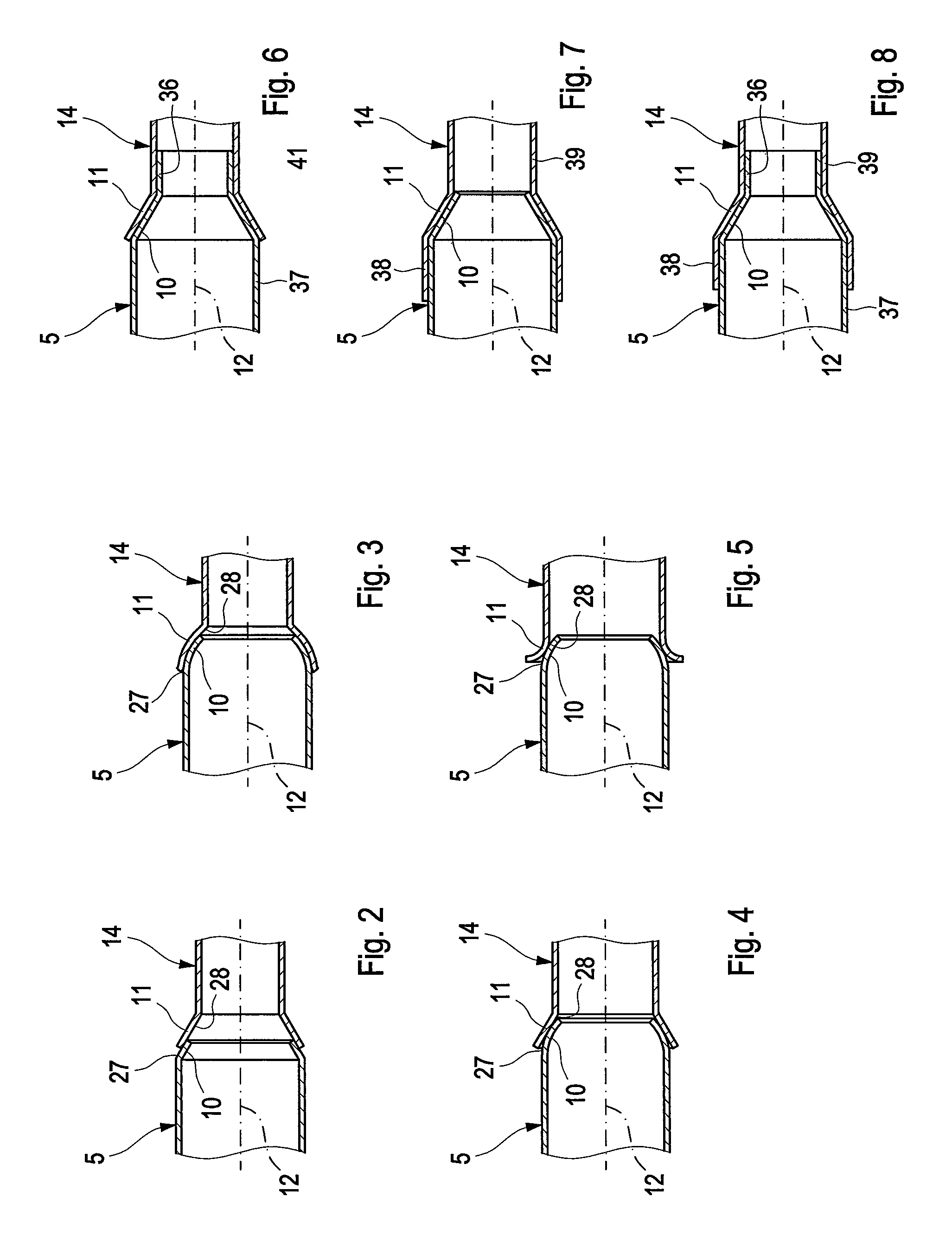
The present invention provides an improved silencer design that is easier to manufacture and has improved stability. The silencer has a cone and a mating cone that support the pipe in the silencer in a radial and axial direction. The cone and mating cone can be easily attached and preload can be adjusted to ensure stability over the entire operating range of the silencer. The cone and mating cone can be designed to compensate for position and shape tolerances. The cone and mating cone can be attached with several protrusions or slits distributed in circumferential direction. These features improve the stability and assembly of the silencer.

Problems solved by technology

This is problematic in connection with the wrap design since this laterally arranged pipe can only be assembled after the insertion of the silencer insert.
This supporting on the silencer insert however can only be realized with difficulty in connection with the wrap design because of the reduced accessibility.

Method used


Image

  • Silencer
  • Silencer
  • Silencer

Examples


Embodiment Construction

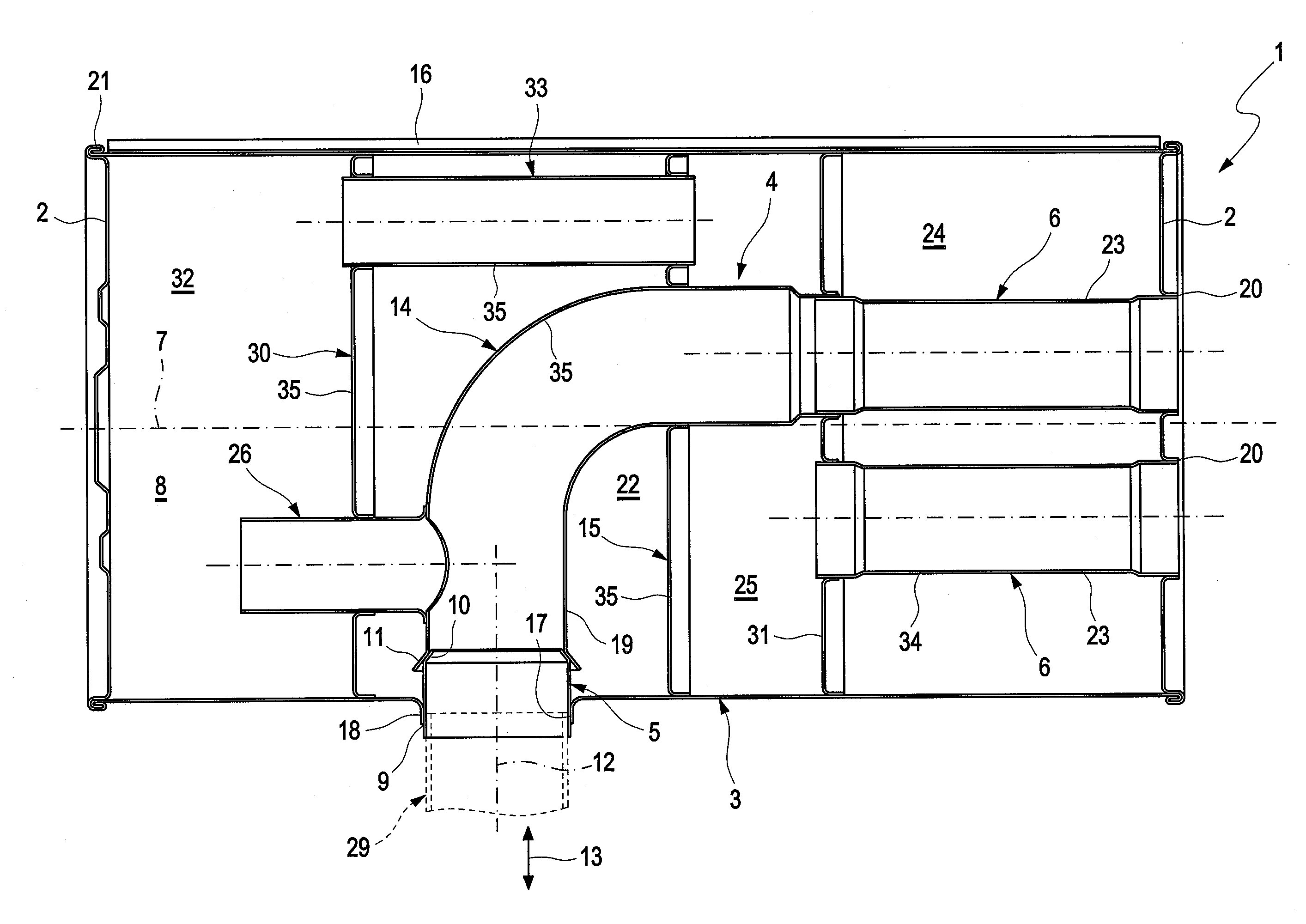
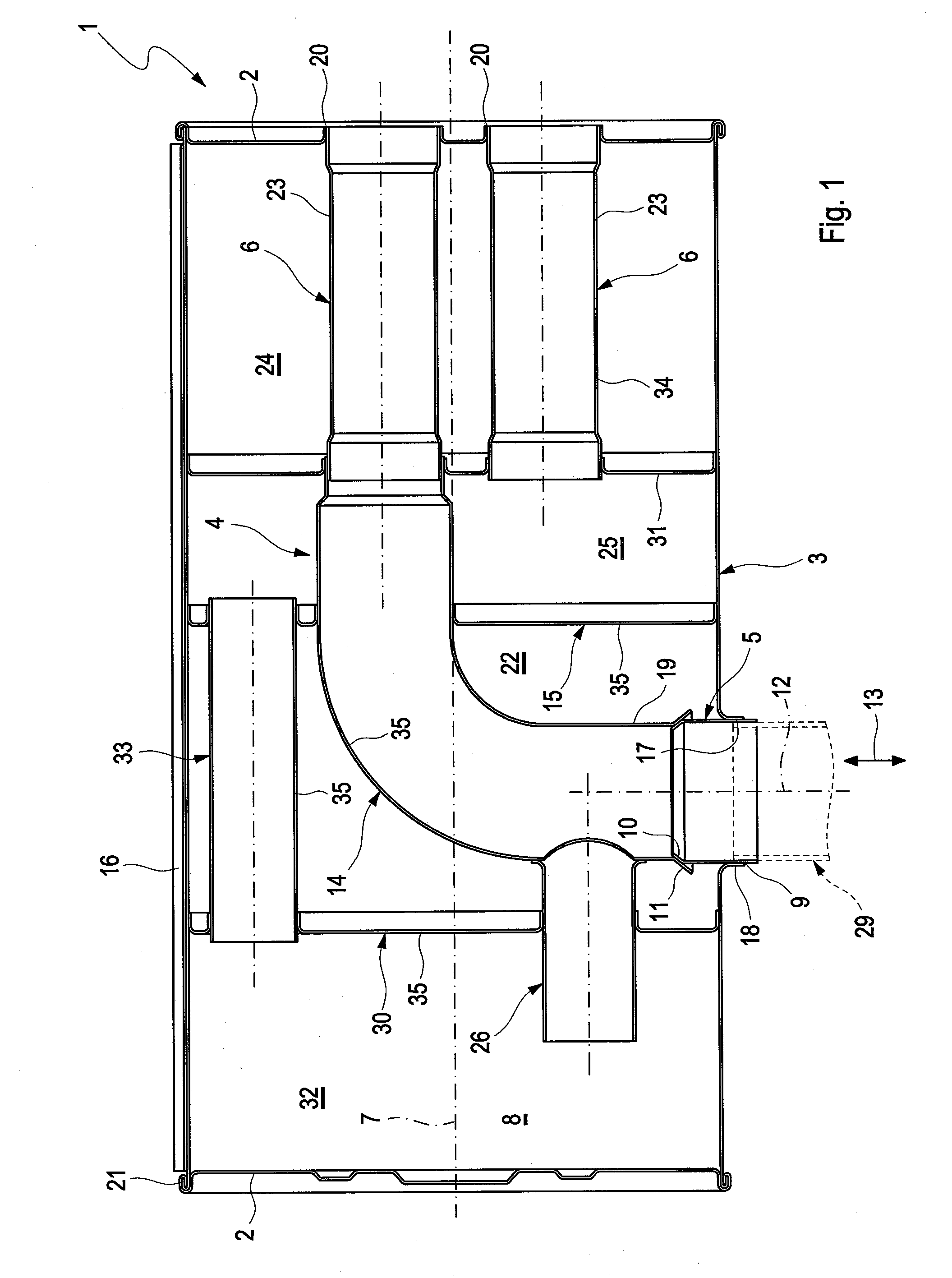
[0030]Referring to the drawings in particular, according to FIG. 1, a silencer 1 comprises two end face bottoms 2 facing away from each other, a closed circumferential jacket 3, at least one silencer insert 4, at least one inlet pipe 5 and at least one outlet pipe 6.

[0031]The silencer 1 is intended for installation in an exhaust system of a combustion engine which is not shown and can more preferably be used in a motor vehicle. Preferentially, the silencer 1 is a rear silencer, that is the silencer which, within the exhaust system or with respect to the exhaust gas flow direction, is the silencer through which the flow flows last before the exhaust gas reaches the respective tailpipe of the exhaust system which comprises the mouth of the exhaust system to the environment. Particularly advantageously the silencer is a silencer arranged positioned horizontally in the assembled state. With the transversely positioned silencer 1 an axial direction 7 of the silencer 1 substantially exten...


PUM

PropertyMeasurementUnit
thermal operatingaaaaaaaaaa
forcesaaaaaaaaaa
stabilityaaaaaaaaaa

Abstract

A silencer for an exhaust system of a combustion engine, more preferably of a motor vehicle, has two end face bottoms facing away from each other, a closed circumferential jacket, at least one silencer insert, at least one inlet pipe and at least one outlet pipe. At least one of the pipes extends through the jacket into the silencer interior and is fastened to the jacket. The manufacture can be simplified if the pipe extending through the jacket has a cone, if the silencer insert on an intermediate pipe has a mating cone which engages in the cone.

Description

CROSS REFERENCE TO RELATED APPLICATIONS[0001]This application claims the benefit of priority under 35 U.S.C. §119 of German Patent Application DE 10 2010 019959.1 filed May 8, 2010, the entire contents of which are incorporated herein by reference.FIELD OF THE INVENTION[0002]The present invention relates to a silencer (also known as a muffler) for an exhaust system of a combustion engine, more preferably of a motor vehicle, with two end face bottoms facing away from each other, with a closed circumferential jacket, with at least one silencer insert, with at least one inlet pipe and with at least one outlet pipe. In addition, the invention relates to an associated manufacturing method.BACKGROUND OF THE INVENTION[0003]Silencers (mufflers) are divided into two manufacturing types with respect to the manufacture of their closed circumferential jacket, namely silencers in shell design and silencers in wrap design. While with the shell design two deep-drawn metal sheets are joined togethe...

Claims


Application Information

Patent Timeline
Patent Type & Authority Patents(United States)
IPC IPC(8): F01N1/02
CPCF01N1/08F01N13/1844Y10T29/49398F01N2470/18Y10T29/49826F01N2450/00F01N1/023
Inventor TAUSCHEK, THOMASSPIETH, ARNULFWIRTH, GEORGE
Owner PUREM GMBH
Learn More