
Dynamic merging of pipeline stages in an execution pipeline to reduce power consumption

a pipeline and pipeline technology, applied in the field of data processing, can solve the problems of appreciable performance penalty, likewise reduced etc., and achieve the effect of reducing power consumption, reducing power consumption of the execution pipeline, and reducing the switching of the latch

Inactive Publication Date: 2012-10-16
INT BUSINESS MASCH CORP
View PDF5 Cites 18 Cited by
  • Summary
  • Abstract
  • Description
  • Claims
  • Application Information

AI Technical Summary

Benefits of technology

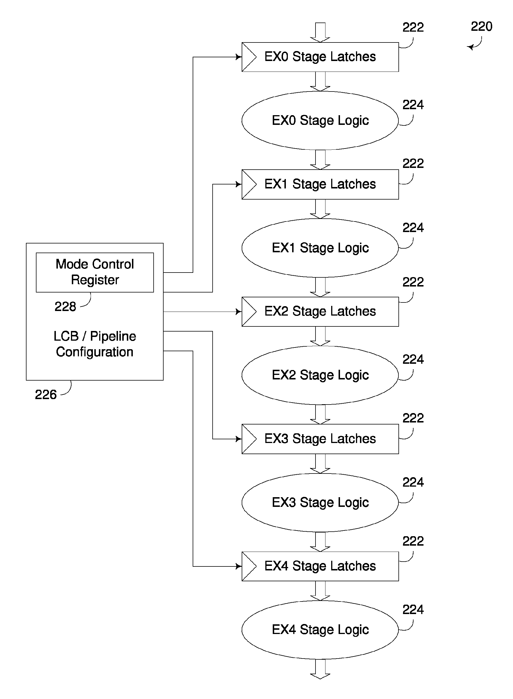
The invention provides a pipelined execution unit that reduces power consumption by dynamically merging pipeline stages in an execution pipeline together with one another. This is achieved by setting one or more latches in alternate pipeline stages in the execution pipeline to a transparent state, and the clock frequency of the execution pipeline is reduced by half. The reduction in power consumption is offset by the reduction in the number of effective stages for the execution pipeline, resulting in approximately the same latency for each instruction processed by the execution pipeline. The invention also includes a circuit arrangement that includes an execution pipeline with multiple pipeline stages and control logic to operate in first and second modes to dynamically merge execution logic and reduce power consumption.

Problems solved by technology

However, with the clock frequency halved, the power consumption of the execution pipeline is likewise reduced approximately by half as well, with the only appreciable penalty in performance being the reduced number of instructions that can be processed in the execution pipeline at the same time.

Method used


Image

  • Dynamic merging of pipeline stages in an execution pipeline to reduce power consumption
  • Dynamic merging of pipeline stages in an execution pipeline to reduce power consumption
  • Dynamic merging of pipeline stages in an execution pipeline to reduce power consumption

Examples


Embodiment Construction

[0029]Embodiments consistent with the invention selectively set latches in the stages of an execution pipeline to a transparent state to dynamically configure the execution pipeline for the purpose of reducing power consumption by the execution pipeline. By setting latches to a transparent stage, the execution logic in the two stages that are otherwise separated by the latches becomes effectively merged so that input data provided to the earlier stage flows through the execution logic of both stages in a single clock cycle. In addition, in many instances, where the combined propagation delay of the merged execution logic exceeds that permitted in a single clock cycle, the frequency of the clock signal provided to the execution pipeline is reduced to accommodate the increased propagation delay.

[0030]In general, an execution pipeline consistent with the invention supports multiple modes. In a normal operating mode, the latches in each pipeline stage are all clocked, e.g., at a first c...


PUM


Abstract

A pipelined execution unit incorporates one or more low power modes that reduce power consumption by dynamically merging pipeline stages in an execution pipeline together with one another. In particular, the execution logic in successive pipeline stages in an execution pipeline may be dynamically merged together by setting one or more latches that are intermediate to such pipeline stages to a transparent state such that the output of the pipeline stage preceding such latches is passed to the subsequent pipeline stage during the same clock cycle so that both such pipeline stages effectively perform steps for the same instruction during each clock cycle. Then, with the selected pipeline stages merged, the power consumption of the execution pipeline can be reduced (e.g., by reducing the clock frequency and / or operating voltage of the execution pipeline), often with minimal adverse impact on performance.

Description

FIELD OF THE INVENTION[0001]The invention is generally related to data processing, and in particular to processor architectures and execution units incorporated therein.BACKGROUND OF THE INVENTION[0002]As semiconductor technology continues to inch closer to practical limitations in terms of increases in clock speed, architects are increasingly focusing on parallelism in processor architectures to obtain performance improvements. At the chip level, multiple processor cores are often disposed on the same chip, functioning in much the same manner as separate processor chips, or to some extent, as completely separate computers. In addition, even within cores, parallelism is employed through the use of multiple execution units that are specialized to handle certain types of operations. Pipelining is also employed in many instances so that certain operations that may take multiple clock cycles to perform are broken up into stages, enabling other operations to be started prior to completio...

Claims


Application Information

Patent Timeline
Patent Type & Authority Patents(United States)
IPC IPC(8): G06F7/38G06F9/44G06F1/32G06F1/26G06F1/00G06F9/00
CPCG06F1/3203G06F1/324G06F1/3296G06F9/38G06F9/3851G06F9/3869G06F9/3873G06F9/3877G06F9/3885Y02B60/1217Y02B60/1285Y02D10/00
Inventor SCHWINN, STEPHEN JOSEPHTUBBS, MATTHEW RAYWAIT, CHARLES DAVID
Owner INT BUSINESS MASCH CORP
Learn More