
Method and system for producing high-pressure hydrogen

a high-pressure hydrogen and hydrogen technology, applied in hydrogen/synthetic gas production, specific gas purification/separation, inorganic chemistry, etc., can solve the problems of difficult support of mea, mechanical properties of membrane, rapid degradation of metallic support structures and compression pads, etc., to reduce faradaic efficiency, reduce current density, and reduce voltage efficiency loss

Inactive Publication Date: 2012-10-09
PLUG POWER
View PDF16 Cites 11 Cited by
  • Summary
  • Abstract
  • Description
  • Claims
  • Application Information

AI Technical Summary

Benefits of technology

[0007]The anticipated benefits of the invention include safety of operation and relative simplicity of constructing a differential-pressure hydrogen compressor cell compared to an electrolyzer with the same pressure difference, which translates into cost savings. The two-cell system of the invention is safer to operate than a high-pressure electrolyzer. Membrane failure in the compressor cell presents little hazard as long as there is a pressure shut off valve, and membrane failure in the low-pressure electrolyzer is less dangerous than it would be in a high-pressure electrolyzer. Thus, the two-cell system allows for the use of thinner membranes, resulting in lower voltage. This compensates for the somewhat higher overall voltage and power inefficiency anticipated when using two cells instead of one. In addition, less risk of explosion exists in recirculating water accumulated at the anode or cathode side of the compressor to the low-pressure electrolyzer of the two-cell system than in feeding a pressurized reactor with cathode water, even if the water contains some hydrogen.
[0009]Further, there are sizable voltage efficiency losses associated with operating a high-pressure (or high-pressure-differential) water electrolyzer, because the oxygen electrode in the water electrolyzer is quite irreversible. Operating the electrolyzer at near atmospheric pressure also allows for the use of lower current densities at the electrolyzer stack without a substantial decrease in faradaic efficiency (efficiency losses due to gas crossover), which is close to 100%. Decreased current density may be achieved by distributing approximately the same amount of electro-catalyst over a larger membrane surface, resulting in higher voltage efficiency of the electrolyzer. These advantages more than compensate for the additional voltage required by the hydrogen compressor cell (which may contribute 5 to 10% to the overall system voltage compared to single cell voltage) and the existence of two stacks versus one.

Problems solved by technology

A water electrolyzer alone could be used to generate hydrogen at high pressure; however, above 2500 psia differential pressure, difficulties arise in supporting the MEA as mechanical properties of the membrane, metallic support structures and compression pads rapidly deteriorate.
A high-pressure PEM electrolyzer is also more expensive than an integrated low-pressure electrolyzer and electrochemical hydrogen compressor.
In addition, small noble metal loadings are required due to the high reversibility of the hydrogen electrode in the absence of carbon monoxide and other inhibiting gas traces.

Method used


Image

  • Method and system for producing high-pressure hydrogen
  • Method and system for producing high-pressure hydrogen
  • Method and system for producing high-pressure hydrogen

Examples


example 1

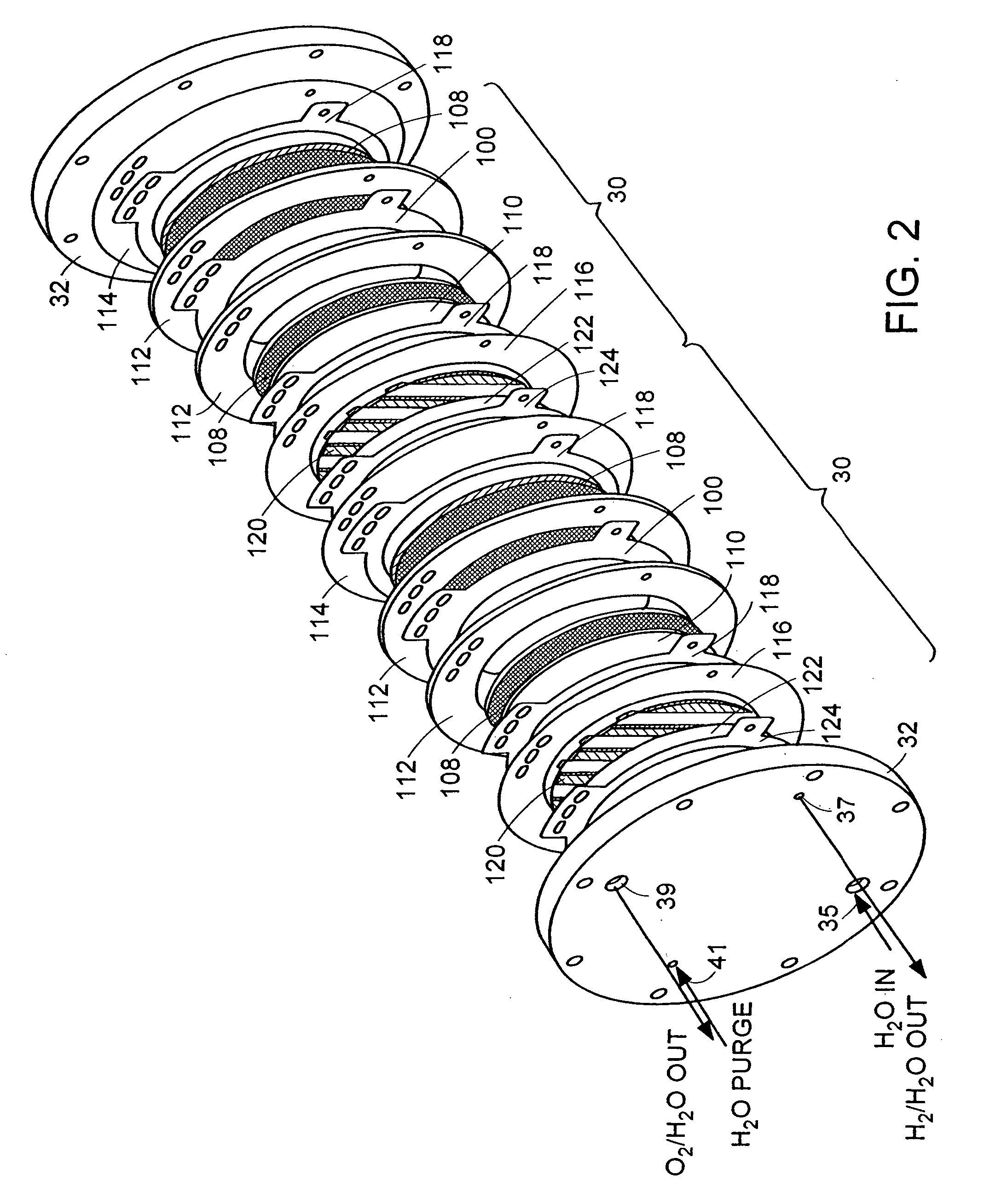
[0046]A hydrogen compressor cell 30 with active cell area of 0.05 ft2 was assembled with a 5-mil (dry) membrane 102 (Dow Chemical, Midland, Mich., Dow XUS 13204), having an equivalent weight of approximately 800 and an ion-exchange capacity (meq of H+ ion / g of dry polymer) of 1.25. Pt black electrode structures 104, 106 were integrally bonded to each surface of the membrane 102. Ambient-pressure hydrogen was fed to the anode 104 of the PEM compressor cell 30, where it was continually oxidized, by the application of a direct electric current from a DC power generator, to form protons, which were electrochemically transported across the membrane 102 to the cathode 106. At the cathode 106, the protons were reduced back to hydrogen, which was allowed to rise to a higher pressure. Because the hydrogen oxidation and reduction reactions are highly reversible, essentially all of the voltage losses were due to current multiplied by ionic resistance. The hydrogen gas was compressed from appro...

example 2

[0047]A hydrogen compressor cell 30 with an active cell area of 0.23 ft2 was assembled with 10-mil (dry) Nafion 120 membrane 102 (E.I. DuPont, Wilmington, Del.) and successfully operated by the application of a direct electric current from a DC power generator at 1000 mA / cm2, compressing hydrogen gas from approximately 15 psia to approximately 1000 psia. Cell voltage was approximately 0.32 V at 40° C.

example 3

[0048]A compressor stack 14 with a 15-mil Nafion membrane 102 (E.I. DuPont, Wilmington, Del.), having a water content of 0.37 g of water per 1 g of dry membrane operates at a differential pressure of 3000 psia (˜200 Atm, a). The compressor stack 14 is integrated with an electrolyzer stack 12 with the same number of cells 30 operating at 80° C. and near-atmospheric pressure, with a current density of 1000 mA / cm2 by the application of a direct electric current from a DC power generator. The hydrogen lost from the high-pressure to the low-pressure side of the compressor stack 14 is 6.7% of the total hydrogen generated; the electrolyzer 12 has a negligible effect on the amount of hydrogen transferred to the low-pressure hydrogen space. The 6.7% hydrogen loss is offset by adding 1 cell per every 15 cells of a theoretical (no hydrogen permeability) compressor stack 14 while leaving the electrolyzer stack 12 untouched.


PUM

PropertyMeasurementUnit
Pressureaaaaaaaaaa
Metallic bondaaaaaaaaaa
Ionic conductivityaaaaaaaaaa

Abstract

Disclosed are methods and systems for generating hydrogen gas at pressures high enough to fill a hydrogen storage cylinder for stationary and transportation applications. The hydrogen output of an electrochemical hydrogen gas generating device, a hydrogen-producing reactor, or a diluted hydrogen stream is integrated with an electrochemical hydrogen compressor operating in a high-differential-pressure mode. The compressor brings the hydrogen produced by the hydrogen generating device to the high pressure required to fill the storage cylinder.

Description

CROSS-REFERENCE TO RELATED APPLICATIONS[0001]This application is a continuation-in-part of U.S. patent application Ser. No. 09 / 942,239, filed on Aug. 29, 2001.FIELD OF THE INVENTION[0002]The present invention relates to systems and methods for generating hydrogen, and more particularly to systems and methods for generating hydrogen gas at pressures high enough to fill gas storage cylinders.BACKGROUND OF THE INVENTION[0003]Hydrogen gas must be generated at high pressures to fill hydrogen storage cylinders for stationary and transportation applications, including on board a vehicle and at refueling stations. To produce hydrogen for use or storage at high pressure, water electrolysis may be performed at the required high pressure, generating both hydrogen and oxygen at high pressure. Alternatively, differential-pressure electrolysis may be employed to generate hydrogen at high pressure and oxygen at substantially atmospheric pressure. To date, high pressure water electrolyzers have bee...

Claims


Application Information

Patent Timeline
IPC IPC(8): C25B1/02C25B1/10C25B1/00C01BC25B1/04C25B1/12C25B11/04C25B15/00
CPCC01B3/503C01B13/0255C25B9/20C25B1/02C25B1/04C25B1/12C25B15/00C25B9/00C01B2203/02C01B2203/0405C01B2203/041C01B2203/0465Y02E60/366C01B2210/0053Y02E60/36C25B9/05C25B9/73B01D53/326
Inventor KOSEK, JOHN A.GINER, JOSELACONTI, ANTHONY B.
Owner PLUG POWER
Learn More