
Chemically-amplified positive resist composition and patterning process thereof

a technology of positive resist and composition, applied in the direction of photosensitive materials, instruments, photomechanical equipment, etc., can solve the problem of too large effective reaction in the catalytic reaction, and achieve the effects of good pattern profile form, good solubility, and little variance in line width and form-deterioration

Active Publication Date: 2012-06-19
SHIN ETSU CHEM CO LTD
View PDF40 Cites 7 Cited by
  • Summary
  • Abstract
  • Description
  • Claims
  • Application Information

AI Technical Summary

Benefits of technology

The resist composition achieves a high resolution, minimal line width variance, and excellent pattern profile stability even with prolonged exposure times, suitable for fine processing and VLSI manufacturing, effectively addressing the limitations of traditional resist compositions.

Problems solved by technology

In this case, however, if a high process temperature is adopted, a diffusion distance of an acid to cause an effective reaction in the catalytic reaction is too large to form a fine pattern with less than 0.1 micrometer, which is presently required for an electron beam lithography.

Method used


Image

  • Chemically-amplified positive resist composition and patterning process thereof
  • Chemically-amplified positive resist composition and patterning process thereof
  • Chemically-amplified positive resist composition and patterning process thereof

Examples


synthesis example 1

Synthesis of Triphenyl Sulfonium Chloride

[0114]Into 400 g of dichloromethane was dissolved 40 g (0.2 mole) of diphenyl sulfoxide, and the resulting solution was agitated under ice-cool. And then, 65 g (0.6 mole) of trimethyl silyl chloride was added dropwise at the temperature not exceeding 20° C., at which temperature the mixture was aged for 30 minutes. Thereafter, a Grignard agent prepared separately from 14.6 g (0.6 mole) of a metal magnesium, 67.5 g (0.6 mol) of chlorobenzene, and 168 g of tetrahydrofurane (THF) was added dropwise into it at the temperature not exceeding 20° C. After the reaction mixture was aged for one hour, it was added by 50 g of water at the temperature not exceeding 20° C. to terminate the reaction, and then further by 150 g of water, 10 g of 12-N hydrochloric acid, and 200 g of diethyl ether. A water layer was taken out by separation and washed by 100 g of diethyl ether to obtain an aqueous triphenyl sulfonium chloride solution. This was used in the subs...

synthesis example 2

Synthesis of 4-tert-butylphenyl diphenyl sulfonium bromide

[0115]The intended compound was obtained by a similar manner to that in Synthesis Example 1 except that 4-tert-butylbromobenzene was used instead of chlorobenzene and the amount of water in the extraction was increased.

synthesis example 3

Synthesis of 4-tert-butoxyphenyl diphenyl sulfonium chloride

[0116]The intended compound was obtained by a similar manner to that in Synthesis Example 1 except that 4-tert-butoxychlorobenzene was used instead of chlorobenzene, a dichloromethane solvent containing 5% by weight of triethylamine was used as the solvent, and the amount of water in the extraction was increased.


PUM

PropertyMeasurementUnit
molecular weight distributionaaaaaaaaaa
temperatureaaaaaaaaaa

Abstract

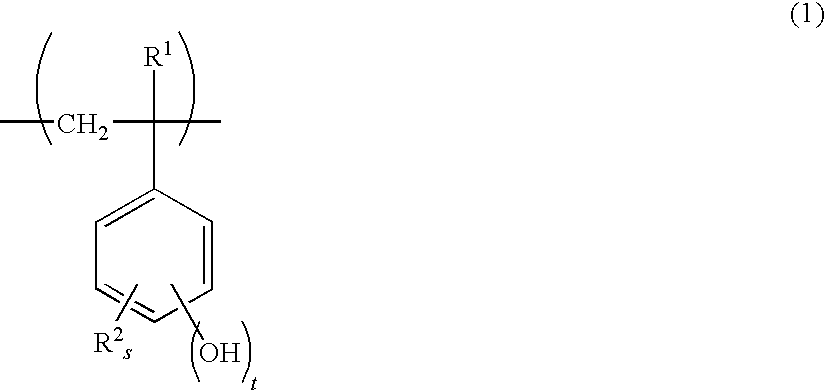
There is disclosed a chemically-amplified positive resist composition comprising, as main components, (A) a base polymer, which contains one or more kinds of a monomer unit represented by the following general formula (1) and the like, and is an alkali-insoluble polymer whose hydroxyl group is partly protected by an acetal group while alkali-soluble when deprotected by an acid catalyst, (B) a sulfonium salt containing a sulfonate anion, (C) a basic component, and (D) an organic solvent. In a lithography technology by a photo resist, an extremely high temporal stability is necessary. In addition, it must give a good pattern profile not dependent on a substrate and have a high resolution power. There can be provided a chemically-amplified positive resist composition which can solve these problems simultaneously, a resist patterning process using the same, and a method for producing a photo mask blank.

Description

BACKGROUND OF THE INVENTION[0001]1. Field of the Invention[0002]The present invention relates to a resist composition of a chemically-amplified which is used for processing of a semiconductor, a photo mask, and so forth, and responds to a high energy radiation such as an UV beam, a deep UV beam, an electron beam, an EUV, an X-ray, an excimer laser, a γ-beam, and a synchrotron beam, in particular to a resist composition of a chemically-amplified type used for a light-exposure by a beam exposure of a high energy radiation including an electron beam and a deep UV beam, and to a resist patterning process using the same.[0003]2. Description of the Related Art[0004]In recent years, as an integrated circuit progresses toward a higher integration, a further finer pattern formation is required, and a chemically-amplified type resist catalyzed by an acid has been mainly used in processing of a pattern with 0.2 micrometer or less. For this, high energy radiations such as an UV beam, a deep UV ...

Claims


Application Information

Patent Timeline
Patent Type & Authority Patents(United States)
IPC IPC(8): G03F7/00G03F7/40G03F7/04G03F7/028
CPCG03F7/0045G03F7/0395G03F7/0392Y10S430/114G03F7/004G03F7/0046G03F7/039
Inventor TAKEDA, TAKANOBUWATANABE, SATOSHIOHSAWA, YOUICHIOHASHI, MASAKIKINSHO, TAKESHI
Owner SHIN ETSU CHEM CO LTD
Learn More