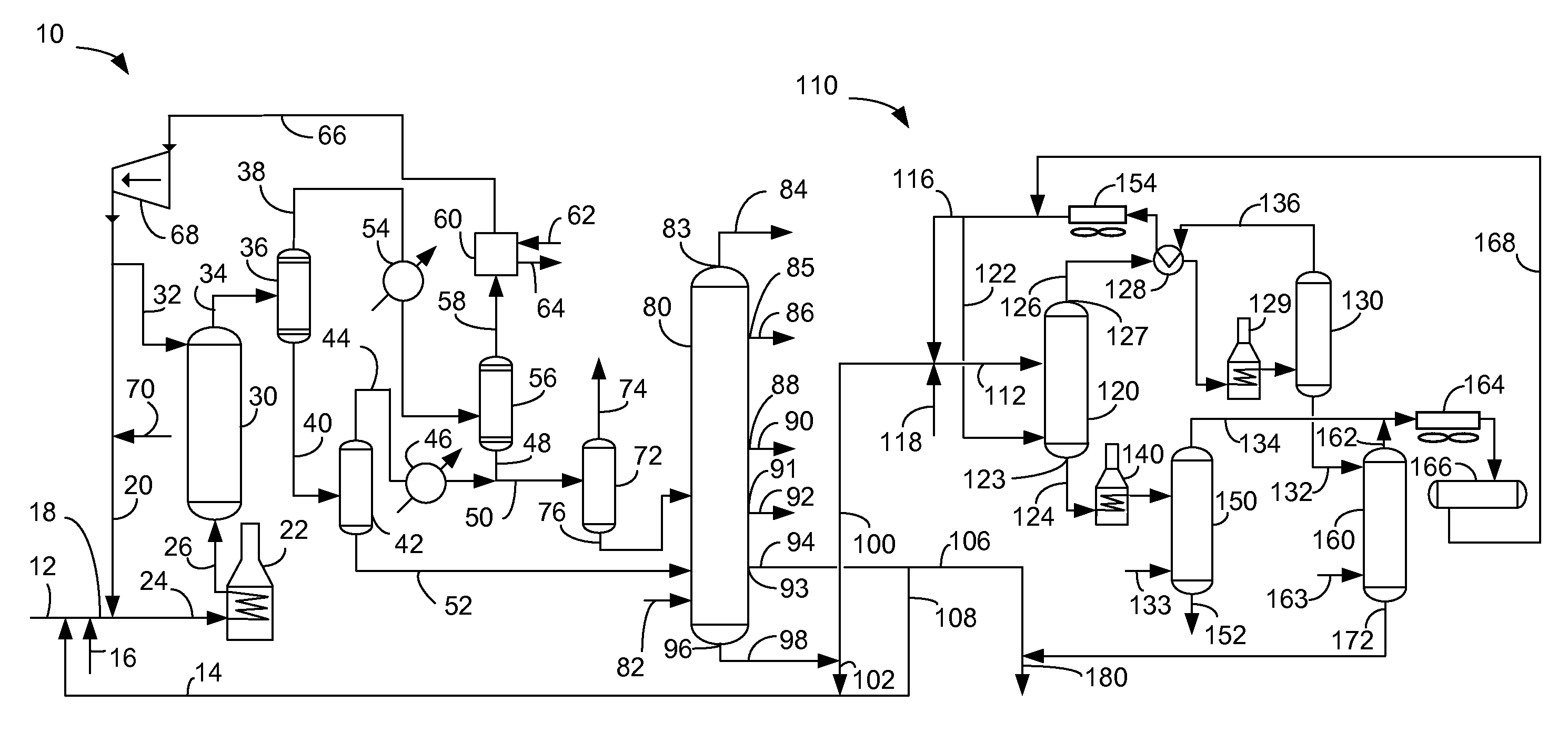
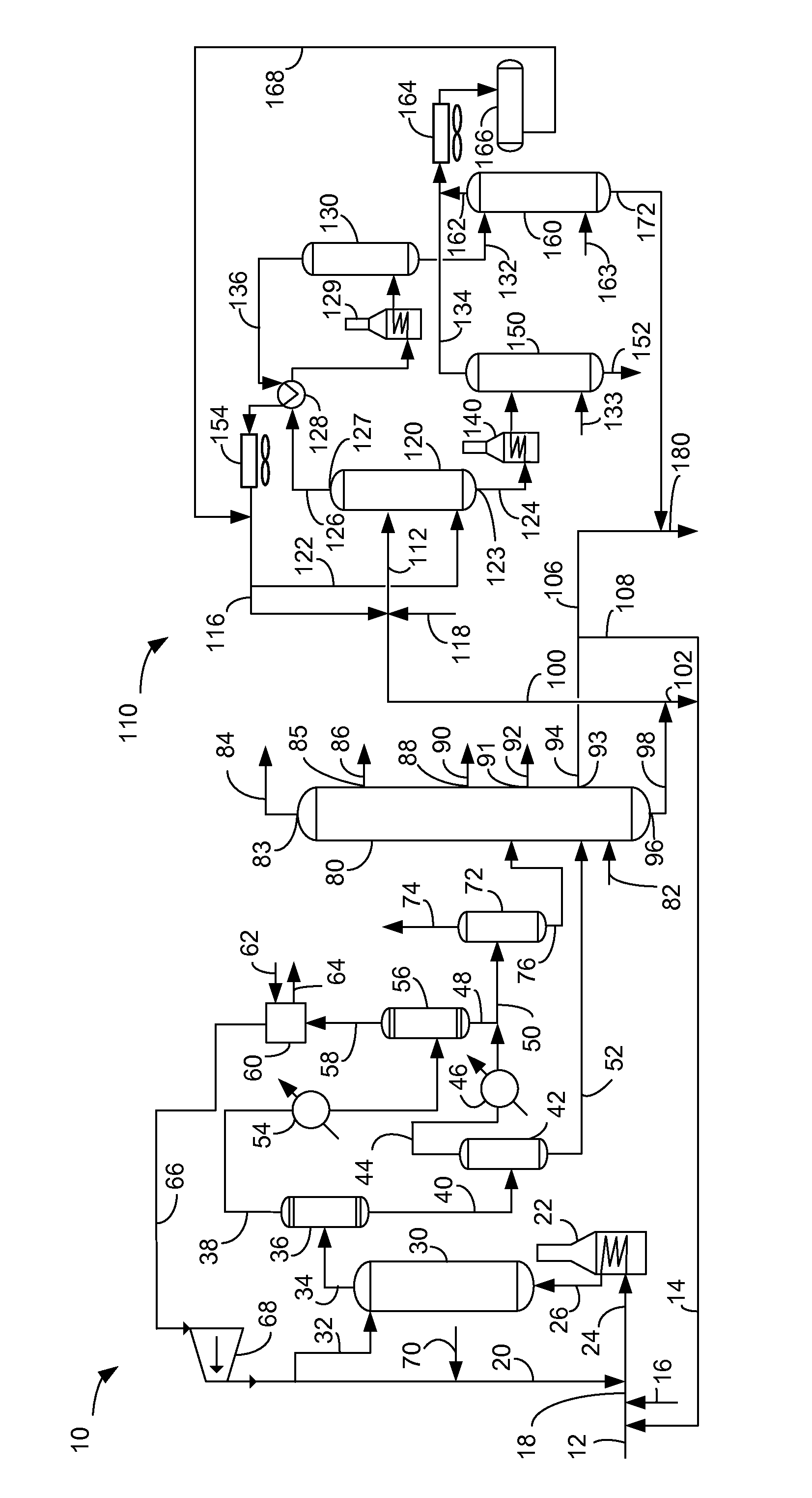
Apparatus for producing hydrocarbon fuel
a technology of hydrocarbon fuel and hydrocarbon fuel, which is applied in the direction of working up pitch/asphalt/bitumen by selective extraction, gas-gas reaction process, physical/chemical process catalyst, etc., can solve the problems of unjustifiable high cost of this process and disadvantag
- Summary
- Abstract
- Description
- Claims
- Application Information
AI Technical Summary
Benefits of technology
Problems solved by technology
Method used
Image
Examples
example 1
[0045]An SHC reactor was used to convert vacuum residue of bitumen from the Peace River formation of Alberta, Canada at a pitch conversion levels of 80 and 90 wt- %. Respective SHC products were separated to provide a pitch product and a HVGO product. Aromatic concentrations were determined for SHC product fractions by ASTM D2549-02 (2007) Standard Test Method for Separation of Representative Aromatics and Nonaromatics Fractions of High-Boiling Oils by Elution Chromatography. Pitch that leaves the SHC reactor is comfortably assumed to be 100% aromatic molecules at all conversion levels above 80 wt- %. Aromatic concentrations that were determined for each HVGO cut are given in Table I.
[0046]
TABLE ISHCConversion,BoilingAromatics,Productwt-%Range, ° C.wt-%HVGO80425-52471.3HVGO90425-52470.8Pitchall524+100
example 2
[0047]An SHC reactor was used to convert the vacuum residue of bitumen from the Peace River formation of Alberta, Canada at a pitch conversion level of 87 wt- %. The SHC product was separated to provide a pitch product and a HVGO product. The pitch product was then subjected to solvent separation using a normal pentane solvent to extract DAO. A blending calculation was conducted to determine properties of a blend of a hydrocarbon composition with selected proportions of the HVGO product and pentane-extracted DAO. The properties of the blended hydrocarbon composition with comparison to the RME180 / IF0180 specification are shown in Table II. The RME180 / IF180 specification is taken from ISO standard 8217:2005(E) Table 2: Requirements for Marine Residual Oils. Aromatic concentrations of the blends in Table II were determined as a weight average of the aromatic concentration in the HVGO and the pitch cuts from Table I.
[0048]
TABLE IIPitch extractMicroHVGOin pentanecarbonPourin blendin blen...
example 3
[0052]An SHC reactor was used to convert vacuum residue of bitumen from Peace River, Alberta, Canada at a pitch conversion level of 87 wt- %. The SHC product was separated to provide a pitch product. The pitch product had the properties given in Table III.
[0053]
TABLE IIIPitch Density, g / cc1.185Nickel, wppm120Vanadium, wppm109
[0054]The pitch product was then subjected to solvent separation using a several solvents to extract DAO. The concentration of metals and density of the pitch lifted by different solvents was examined and shown in Table IV.
[0055]
TABLE IVSolventNickel +ExtractedDensity,ExtractedNickel,Vanadium,Vanadium,oil density,Solventg / ccoil wt-%wppmwppmwppmg / ccpentane0.631215.77.03.010.01.074hexane0.664025.120.714.535.21.079heptane0.688232.431.622.554.11.082toluene0.871981.599.093.0192.01.057
[0056]In this experiment, the nickel and vanadium concentrations in the extracted oil were found to be linear with either solvent density or wt- % yield. Hexane was not actually tested b...
PUM
| Property | Measurement | Unit |
|---|---|---|
| temperature | aaaaa | aaaaa |
| pressures | aaaaa | aaaaa |
| particle sizes | aaaaa | aaaaa |
Abstract
Description
Claims
Application Information
 - R&D
- Intellectual Property
- Life Sciences
- Materials
- Tech Scout
- Unparalleled Data Quality
- Higher Quality Content
- 60% Fewer Hallucinations
Browse by: Latest US Patents, China's latest patents, Technical Efficacy Thesaurus, Application Domain, Technology Topic, Popular Technical Reports.
© 2025 PatSnap. All rights reserved.Legal|Privacy policy|Modern Slavery Act Transparency Statement|Sitemap|About US| Contact US: help@patsnap.com


