
Removal of particulates from the exhaust gas of internal combustion engines operated with a predominantly stoichiometric air/fuel mixture

a technology of stoichiometric air/fuel mixture and particulate filter, which is applied in the direction of engine components, combustible gas purification, phosphorus compounds, etc., can solve the problems of not meeting the requirements of catalytically activated diesel particulate filters known in the prior art, difficult to achieve temperatures above 400° c. in the downstream exhaust gas system, etc., to achieve high thermal cycling stability and sufficient thermal aging stability

Active Publication Date: 2011-11-29
UMICORE AG & CO KG
View PDF12 Cites 55 Cited by
  • Summary
  • Abstract
  • Description
  • Claims
  • Application Information

AI Technical Summary

Benefits of technology

The solution provides enhanced removal of particulates and gaseous pollutants, ensuring compliance with future emissions standards and maintaining catalytic activity even after thermal aging, with improved soot burnoff and three-way catalytic activity.

Problems solved by technology

The lowering of the soot ignition temperature is of particular significance in the case of use of particulate filters to clean diesel exhaust gases, since, owing to the “cold” combustion profile in the diesel engine, the implementation of temperatures above 400° C. in the downstream exhaust gas system is frequently difficult.
This leads to the effect that not all filter bodies known in the prior art are suitable for cleaning the exhaust gas to very substantially eliminate particulate emissions, and it is instead necessary to use substrates which are not permeable even to ultrafine particulates.
The catalytically activated diesel particulate filters known from the prior art generally do not satisfy these requirements.

Method used


Image

  • Removal of particulates from the exhaust gas of internal combustion engines operated with a predominantly stoichiometric air/fuel mixture
  • Removal of particulates from the exhaust gas of internal combustion engines operated with a predominantly stoichiometric air/fuel mixture
  • Removal of particulates from the exhaust gas of internal combustion engines operated with a predominantly stoichiometric air/fuel mixture

Examples


example

[0070]Manufacture of the First Layer:

[0071]Alumina (specific surface area 140 m2 / g) stabilized with 3% by weight of lanthanum oxide and a cerium / zirconium mixed oxide with a cerium oxide content of 40% by weight was activated according to U.S. Pat. No. 6,103,660 using barium hydroxide as a base together with palladium originating from palladium nitrate. The resulting suspension was used directly to coat the wall flow filter substrate. The suspension was applied only in the inflow channels of the filter body. After the coating, the filter was dried and calcined. The finished first layer contained the following amounts of coating:

[0072]

10g / lof lanthanum-stabilized alumina10g / lof cerium / zirconium mixed oxide with 40% byweight of cerium oxide1g / lof barium oxide1.236g / lof palladium (on all components)

[0073]Manufacture of the Second Layer:

[0074]A cerium / zirconium mixed oxide with a cerium oxide content of 20% by weight was suspended in water. Thereafter, an aqueous solution of rhodium nit...


PUM

PropertyMeasurementUnit
exhaust gas temperaturesaaaaaaaaaa
particle sizeaaaaaaaaaa

Abstract

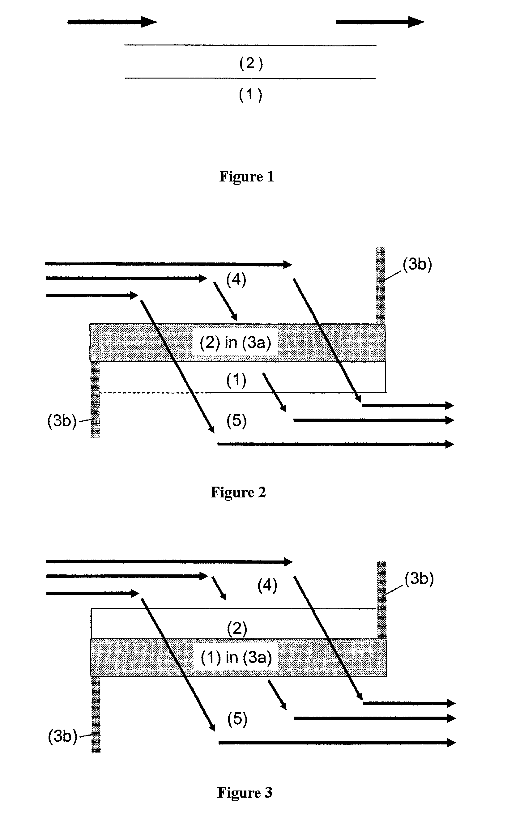
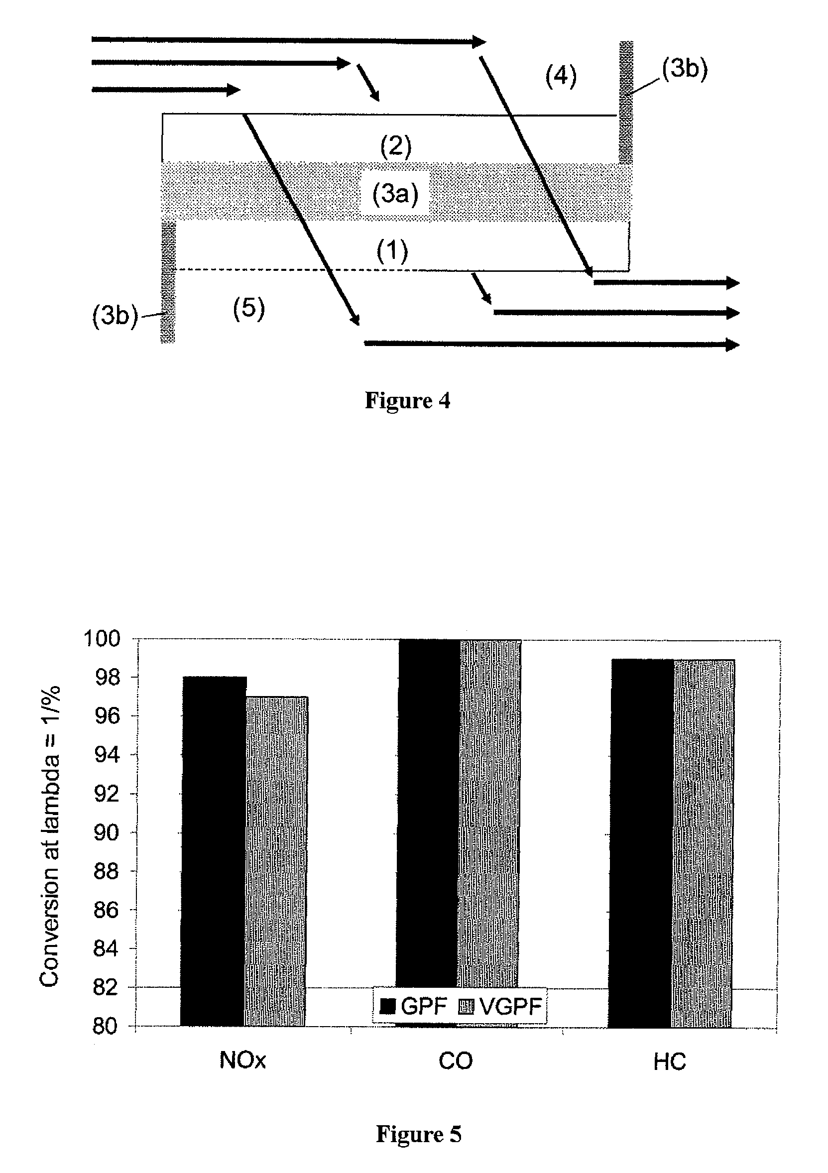
The exhaust gas of internal combustion engines operated with a predominantly stoichiometric air / fuel mixture contains, as well as the gaseous hydrocarbon (HC), carbon monoxide (CO) and nitrogen oxide (NOx) pollutants, also ultrafine particulates. There is disclosed a catalytically active particulate filter, an exhaust gas cleaning system and a process for cleaning the exhaust gases of predominantly stoichiometrically operated internal combustion engines, as well as the gaseous CO, HC and NOx pollutants, also for removing particulates from the exhaust gas. The particulate filter comprises a filter body and a catalytically active coating consisting of two layers. Both layers contain alumina. The first layer contains palladium. The second layer contains rhodium. The latter is disposed above the first layer.

Description

[0001]The invention relates to a catalytically active particulate filter which is suitable especially for the removal of particulates from the exhaust gas of internal combustion engines operated predominantly with a stoichiometric air / fuel mixture, to a process for removing particulates, carbon monoxide, hydrocarbons and nitrogen oxides from the exhaust gas of internal combustion engines operated with a predominantly stoichiometric air / fuel mixture, and a device suitable for this purpose.[0002]Exhaust gases from internal combustion engines operated with a predominantly stoichiometric air / fuel mixture are cleaned in conventional methods with the aid of three-way catalytic converters. These are capable of converting the three essentially gaseous pollutants of the engine, specifically hydrocarbons, carbon monoxide and nitrogen oxides, simultaneously to harmless components. Apart from the gaseous hydrocarbon (HC), carbon monoxide (CO) and nitrogen oxide (NOx) pollutants, the exhaust gas...

Claims


Application Information

Patent Timeline
Patent Type & Authority Patents(United States)
IPC IPC(8): B01J8/00B01J23/44B01J23/46
CPCB01D53/944B01D53/945B01J23/002B01J23/63B01J35/023B01J35/04B01J37/0244F01N3/035B01D2255/1023B01D2255/1025B01D2255/407B01D2255/9022B01D2255/908B01D2258/014B01J2523/00F01N2510/06B01J2523/25B01J2523/31B01J2523/3706B01J2523/3712B01J2523/48B01J2523/824B01J2523/822Y02T10/22Y02A50/20Y02T10/12B01J35/40B01J35/56
Inventor KLINGMANN, RAOULROESCH, MARTINLINDNER, DIETER
Owner UMICORE AG & CO KG
Learn More