
Electrochemical gas sensor containing electric connection lines or housing contact bridges comprising carbon nanotubes

a carbon nanotube and gas sensor technology, applied in the field of electrochemical gas sensors, can solve the problems of reducing the cross sensitivity of materials in contact with electrolyte, oxidizing over time, and reducing the potential window

Active Publication Date: 2011-07-19
DRAGERWERK AG
View PDF21 Cites 2 Cited by
  • Summary
  • Abstract
  • Description
  • Claims
  • Application Information

AI Technical Summary

Benefits of technology

The present invention provides an electrochemical gas sensor with improved cross sensitivity, a wide potential window, and durable electrolyte-tight contacting through or via the housing. The sensor has electric connection elements made of carbon nanotubes, which have good electrical conductivity and lower catalytic activity compared to precious metals and carbon fibers. The carbon nanotubes can be used in the housing as electric connection lines or as housing contact bridges. The sensor also has a measuring electrode and a counterelectrode, which are designed to have good electrical contact with the electrodes. The carbon nanotubes can be applied to the housing parts using an ink jet printing method. The sensor can be used with a diaphragm and a diffusion membrane. The housing parts forming electrically conductive housing contact bridges with the electrodes can be snapped into a protective sleeve or welded into a housing pot. The sensor has a wide potential window and is durable, making it suitable for various gas sensing applications.

Problems solved by technology

However, a number of drawbacks are also associated with the use of precious metal drain wires.
These gas sensors are not selective but always detect a plurality of gases due to the high catalytic activity of their measuring electrodes.
The surface of the likewise catalytically active contacting wires, which is small compared to this, therefore makes a nearly unmeasurable contribution to the signal current.
The last, catalytically active component in the area of the measuring electrodes of these gas sensors is the precious metal drain wire, which, acting practically as an electrode, now represents the essential disturbance in respect to the above-described problems.
Even though this situation can be improved by the use of graphite, carbon fibers or glass carbon for contacting the measuring electrode, it cannot be solved, because these materials also have some interfering cross sensitivities, e.g., for nitrogen oxides.
Moreover, these materials, which are in contact with the electrolyte, are oxidized over time and lose contact with the measuring electrode.
However, there also are problems concerning the tightness of the connection lines through the housings of such electrochemical gas sensors because, for example, oxygen is formed at the counterelectrode and the contacting wire thereof in oxygen sensors, so that a tightness problem develops at the site at which the contact wire is led through the housing because the plastic surrounding the metal wire and thus exerting a sealing action is progressively degraded by oxidation due to the evolution of gas and the electrolyte can flow out of the housing along the gap thus formed.
Another cause of leaks is the different coefficients of expansion of precious metal wires and the plastic housing, so that capillary gaps, through which the electrolyte can flow out, are formed over time at the openings through which the wire is led out of the housing for this reason as well.
To overcome these drawbacks, special liquid and labyrinth sealing systems are used, which are associated with additional working steps and material consumption and continue to cause problems in practice because of the different materials used and the temperature changes occurring.
The alternative use of a conductive composite plastic injected into the sensor housing as a substitute for the draining connection lines has also failed to prove successful because the electric conductivity of these plastics declines over time since the components responsible for the conductivity, such as graphite or carbon fibers, undergo oxidation and thus develop a high ohmic resistance.

Method used


Image

  • Electrochemical gas sensor containing electric connection lines or housing contact bridges comprising carbon nanotubes
  • Electrochemical gas sensor containing electric connection lines or housing contact bridges comprising carbon nanotubes
  • Electrochemical gas sensor containing electric connection lines or housing contact bridges comprising carbon nanotubes

Examples


Embodiment Construction

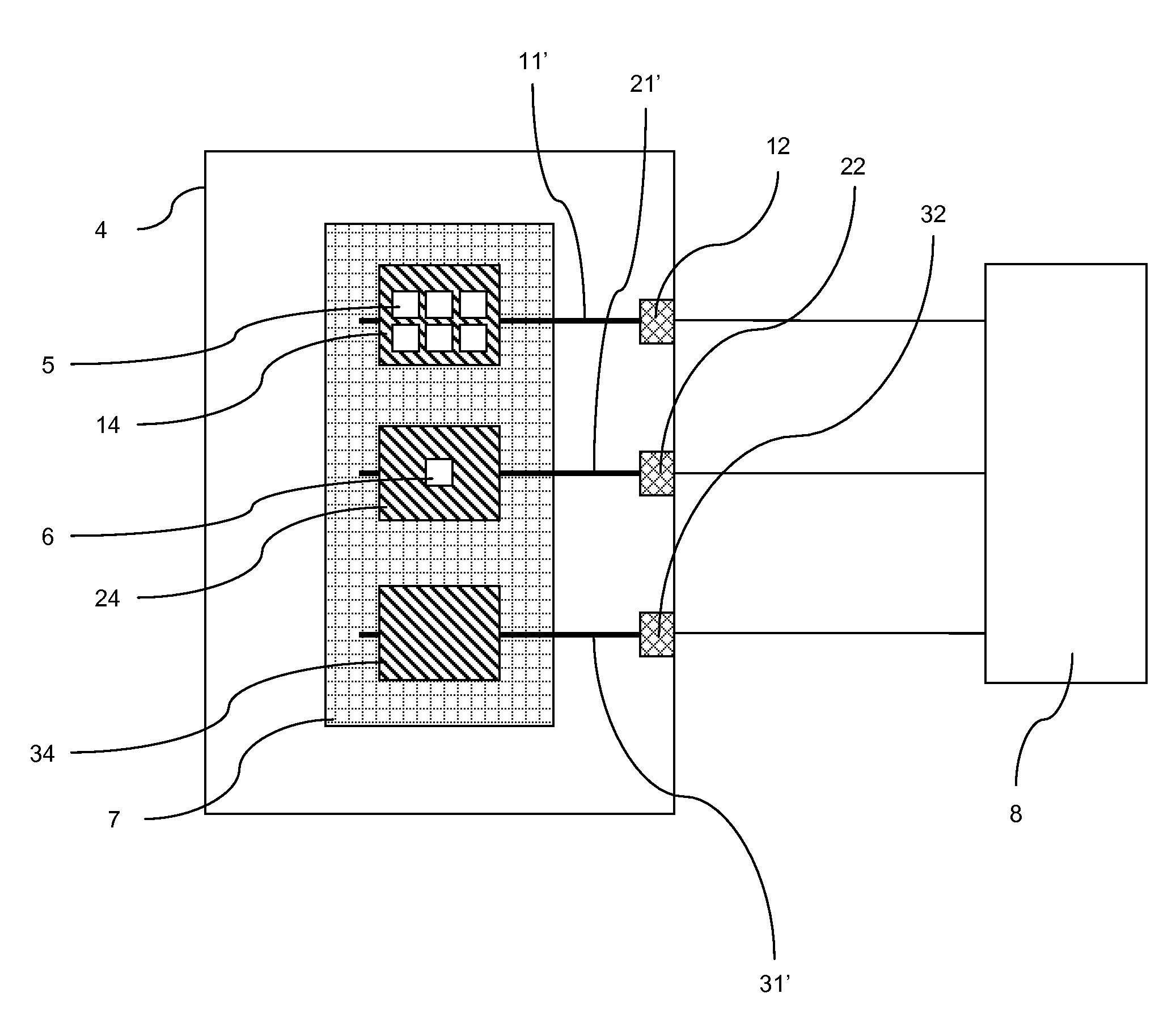
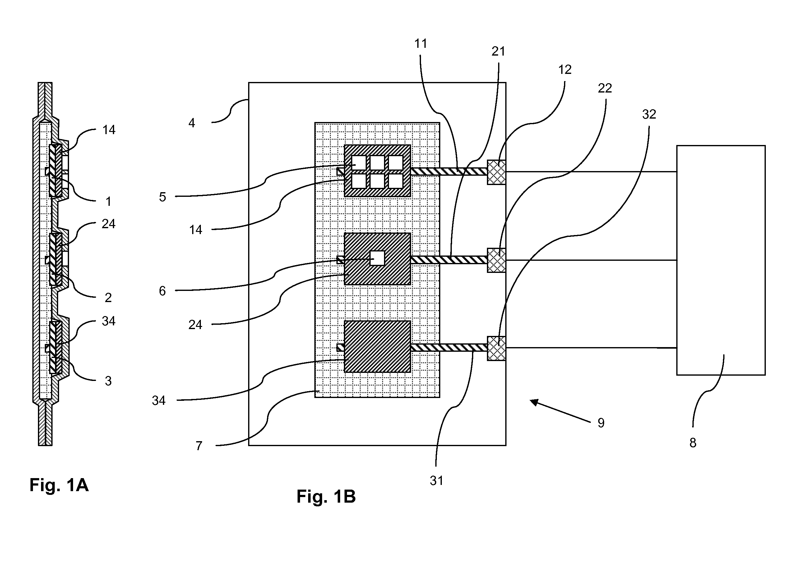
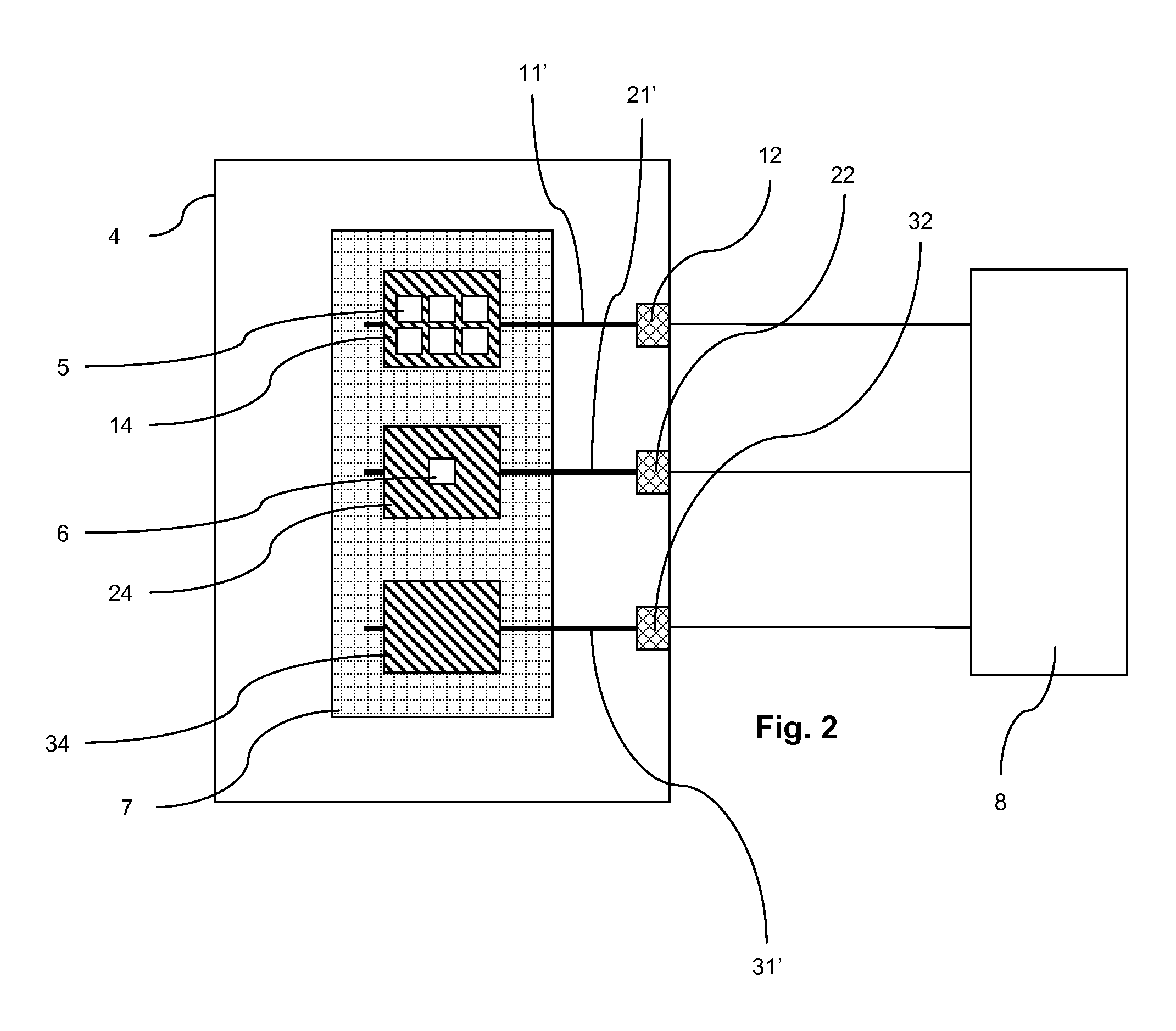
[0037]Referring to the drawings in particular, chip-like and planar, flat electrochemical gas sensors 9, whose housing 4 is formed by welded or laminated films comprising a plastic, are shown as examples each in FIGS. 1 through 3.

[0038]The electrochemical gas sensor 9 in FIG. 1B has a measuring electrode 1 comprising diamond-like carbon (DLC), a counterelectrode 2 comprising nickel, and a reference electrode 3 comprising platinum.

[0039]All electrodes 1, 2, 3 have perfluorinated polymer diffusion membranes 14, 24, 34.

[0040]The connection lines 11, 21, 31 comprising single wall carbon nanotubes (SWCNT), which are strip-shaped here, are located between the contact pads 12, 22 and 32 and the electrodes 1, 2, 3. The gas inlet openings 5 to the measuring electrode 1 and the gas outlet openings 6 to the counterelectrode 2 are formed by corresponding patterns in the upper housing film.

[0041]The electrolyte, especially an aqueous lithium bromide solution for the electrochemical detection rea...


PUM

PropertyMeasurementUnit
areaaaaaaaaaaa
electrically conductiveaaaaaaaaaa
electricallyaaaaaaaaaa

Abstract

An electrochemical gas sensor (9) has improved electrochemical measurement properties and housing tightness for an electrolyte at the sites at which the connection lines (11, 21, 31) pass through. The sensor (9) includes a housing (4), containing at least one measuring electrode (1) and a counterelectrode (2) and with electric connection lines (11, 21, 31) from the electrodes (1, 2, 3) to a measuring unit (8) arranged outside the housing (4). The electric connection lines (11, 21, 31) include carbon nanotubes (CNT, Carbon Nanotubes) at least in some sections in the housing (4) in the area of the electrolyte wetting.

Description

CROSS REFERENCE TO RELATED APPLICATIONS[0001]This application claims the benefit of priority under 35 U.S.C. §119 of German Patent Application DE 10 2006 054 948.1 filed Nov. 22, 2006, the entire contents of which are incorporated herein by reference.FIELD OF THE INVENTION[0002]The present invention pertains to an electrochemical gas sensor containing housing parts from carbon nanotubes, which housing parts form electric connection lines or housing contact bridges.BACKGROUND OF THE INVENTION[0003]Electrochemical gas sensors usually have a housing with at least one measuring electrode and a counterelectrode in an electrolyte and with electric connection lines from the electrodes to a measuring unit arranged, in general, outside the housing, wherein the measuring unit is usually a potentiostat with an evaluating circuit. The connection lines are contacted with the electrodes in the known manner in the form of drain wires made especially of precious metals such as platinum, because the...

Claims


Application Information

Patent Timeline
Patent Type & Authority Patents(United States)
IPC IPC(8): G01N27/407
CPCB82Y15/00B82Y30/00G01N33/0009Y10S977/953G01N27/28G01N27/403G01N27/413
Inventor METT, FRANK
Owner DRAGERWERK AG
Learn More