
Microelectronic sensor device with an out-of-plane detection having a controlled cross sensitivity

a microelectronic sensor and out-of-plane detection technology, applied in piezoelectric/electrostrictive devices, chemical vapor deposition coatings, decorative arts, etc., can solve the problems of non-zero differential stress, increased production cost and bulk, and cross sensitivity not controlled

Active Publication Date: 2021-04-06
COMMISSARIAT A LENERGIE ATOMIQUE ET AUX ENERGIES ALTERNATIVES
View PDF5 Cites 2 Cited by
  • Summary
  • Abstract
  • Description
  • Claims
  • Application Information

AI Technical Summary

Benefits of technology

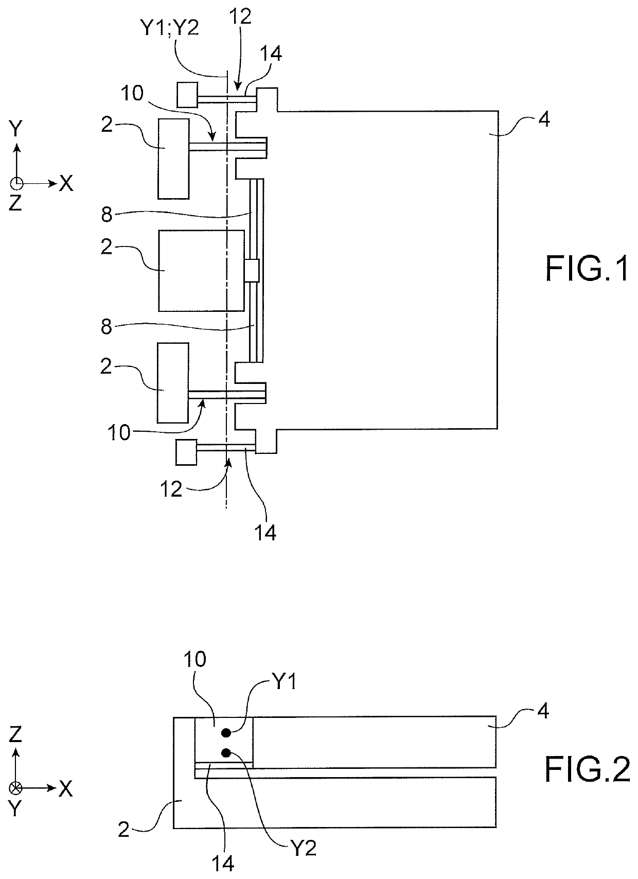
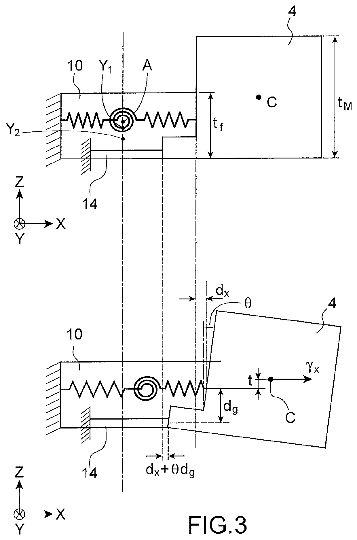
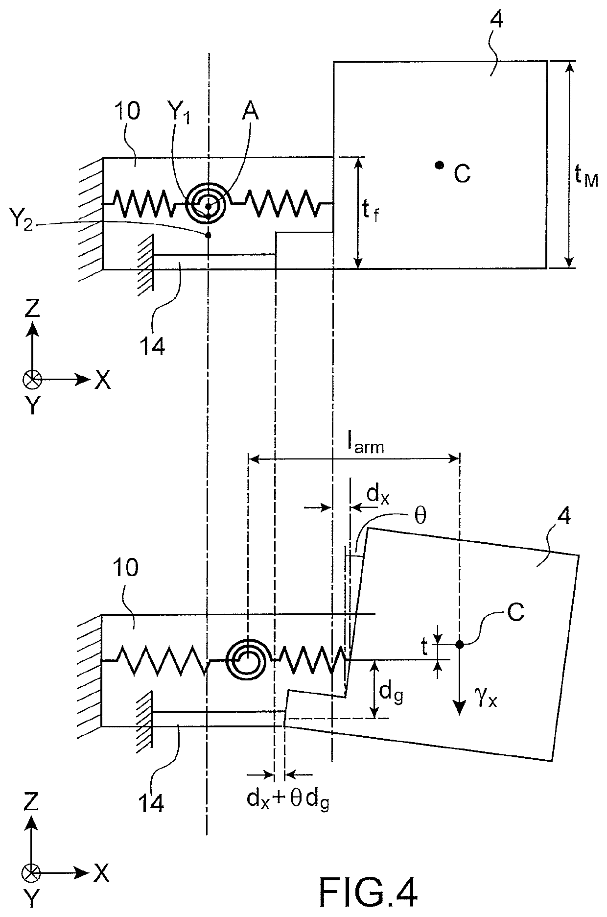
The present invention offers a microelectromechanical and nanoelectromechanical sensor with high sensitivity in the out-of-plane direction and cross sensitivity controlled in a simple manner. The sensor structure is designed to have the expected specifications in terms of cross sensitivity. The mass is stressed about two different axes of rotation according to whether the stress is in the out-of-plane direction or in a direction contained in the plane. The inventors have determined that they could design a structure in such a way that the axis of rotation of the structure, when it is subjected to a stress in the plane, moves towards the middle plane of the stress gauge or of stress gauges. The cross sensitivity of the structure is thus reduced. The invention allows for controlling or even avoiding the error due to the cross sensitivity of the sensor without implementing a second sensor.

Problems solved by technology

These effects do not compensate for each other in general, this results in a non-zero differential stress in the gauges and thus a sensitivity of the sensor to a stress in the direction orthogonal to the out-of-plane direction and to the axis of the pivot.
Moreover this cross sensitivity is not controlled.
It is possible to overcome this parasite sensitivity, in the case in which the sensor with an out-of-plane detection is associated with at least one sensor with detection in the crosswise direction, indeed in this case the error due to the parasite sensitivity can be corrected, however this solution imposes the implementation of a second sensor, which increases the production cost and the bulk, and this results in a complexification of the electronics required.

Method used


Image

  • Microelectronic sensor device with an out-of-plane detection having a controlled cross sensitivity
  • Microelectronic sensor device with an out-of-plane detection having a controlled cross sensitivity
  • Microelectronic sensor device with an out-of-plane detection having a controlled cross sensitivity

Examples


Embodiment Construction

[0012]It is therefore a goal of the present invention to offer a microelectromechanical and nanoelectromechanical sensor offering both a high sensitivity in the out-of-plane direction and a cross sensitivity controlled in a simple manner.

[0013]The goal stated above is achieved by a microelectromechanical and nanoelectromechanical sensor comprising a structure comprising a mass suspended from a support by suspension means in such a way as to be mobile in an out-of-plane direction, said suspension means comprising at least one beam stressed by bending. The sensor also comprises means for detection of the out-of-plane movement of the mass, comprising at least one stress gauge suspended between the support and the mass and extending orthogonally to the axis of rotation. The thickness of at least the bending beam is thus chosen with respect to the thickness of the mass, according to the cross sensitivity which is accepted for the sensor.

[0014]Indeed, the inventors have determined, in a s...


PUM

PropertyMeasurementUnit
thicknessaaaaaaaaaa
thickness tfaaaaaaaaaa
thicknessaaaaaaaaaa

Abstract

Microelectromechanical sensor with an out-of-plane detection has a cross sensitivity in a first direction in the plane with a value of ST, the sensor comprising a support, a mass suspended from the support by beams stressed by bending, in such a way that the inertial mass is capable of moving with respect to the support about an axis of rotation contained in a plane of the sensor, a stress gauge suspended between the mass and the support. The bending beams have a dimension tf in the out-of-plane direction and the mass has a dimension tM in the out-of-plane direction such thattf=34⁢(tM-2⁢larm⁢ST).Larm is the distance between the centre of gravity of the mass and the centre of the bending beams projected onto the first direction.

Description

TECHNICAL FIELD AND PRIOR ART[0001]The present invention relates to a sensor with a microelectromechanical and nanoelectromechanical structure or MEMS&NEMS (microelectromechanical and nanoelectromechanical systems) with an out-of-plane detection.[0002]MEMS&NEMS sensors with an out-of-plane detection are for example used to realise accelerometers, gyrometers, force or magnetic-field sensors. They comprise a mass suspended with respect to a support, which is intended to have an out-of-plane movement, i.e. substantially orthogonal to the plane of the sensor, under the effect of an outside force for example an acceleration or a Coriolis force.[0003]The document FR 3 000 050 describes a microelectromechanical device used as a force sensor, comprising a mass suspended from a support by at least one beam intended to be deformed by bending and beams intended to be deformed by torsion. The beams define an axis of rotation and the mass pivots about this axis under the effect of an outside for...

Claims


Application Information

Patent Timeline
Patent Type & Authority Patents(United States)
IPC IPC(8): B81B3/00B81C1/00H10N30/03
CPCB81B3/0072B81C1/0015B81B2201/0235B81B2201/0242B81B2201/0292B81B2203/0118B81B2203/056B81B3/0048B81B2201/025B81B2203/019
Inventor JOET, LOICREY, PATRICE
Owner COMMISSARIAT A LENERGIE ATOMIQUE ET AUX ENERGIES ALTERNATIVES
Learn More