Method for manufacturing a three-dimensional forming portion

a three-dimensional forming and manufacturing technology, applied in the field of three-dimensional forming portions, can solve the problems of forming windows by fracturing, cracks and burrs, and rough fracture surfaces, and achieve the effects of short time, short time required for post-dried three-dimensional forming steps, and increased adhesion between ceramic green sheets and slurry

Inactive Publication Date: 2011-06-07
NGK INSULATORS LTD
View PDF22 Cites 4 Cited by
  • Summary
  • Abstract
  • Description
  • Claims
  • Application Information

AI Technical Summary

Benefits of technology

[0008]In view of the above, the inventors have perceived, as a result of their study, that the problems caused by the punching through process can be avoided, when a small size three-dimensional portion (convex portion) is formed on a ceramic green sheet without using the punching through process, because the laminated body having “the ceramic green sheet having the window section” placed on “the ceramic green sheet serving as the substrate” has the same structure as a body having “the three-dimensional portion (convex portion) with a desired pattern” formed on “the ceramic green sheet serving as the substrate”. Accordingly, one of objects of the present invention is to provide a method for manufacturing a three-dimensional forming portion by which “a three-dimensional forming portion (convex portion), having a desired shape such as fine patterns and the like” can be “formed easily with high precision” on one surface side of surfaces of a porous substrate, by taking advantage of a character of the porous substrate.
[0052]With the feature above, it is possible to evaporate the solvent permeated into the fine pores of the porous substrate in a short time. As a result, a time required for the post-dried three dimensional forming portion forming step can be shortened. Further, if the porous substrate is a ceramic green sheet, it is possible to raise a temperature of the ceramic green sheet above the glass-transition temperature by heating the ceramic green sheet. In such a case, the ceramic green sheet is softened, and thus an adherence between the ceramic green sheet and the slurry can be increased.

Problems solved by technology

However, according to the punching through process with using a tool punch and a die, the window section is formed by fracturing or tearing.
As a result, a portion close to the window section and the fracture surfaces of the window section may be deformed, the fracture surfaces may become rough, or a crack and a burr may be created at the punched-through portion, when the punch-through-pitch (distance between one window section and another window section adjacent to the one window section) is small or when a thickness of the ceramic green sheet is large, etc.
The deformation, the burr, or the crack and the like have more adverse effects on a shape accuracy of the hollow portion, as the hollow portion becomes more miniaturized.
It is difficult to make “the tool punch and the die” which are very small from the materials having high hardness.
Thus, there is a limit for miniaturizing “the tool punch and the die”.

Method used


Image

  • Method for manufacturing a three-dimensional forming portion
  • Method for manufacturing a three-dimensional forming portion
  • Method for manufacturing a three-dimensional forming portion

Examples


first embodiment

[0074](A Mold Preparation Step)

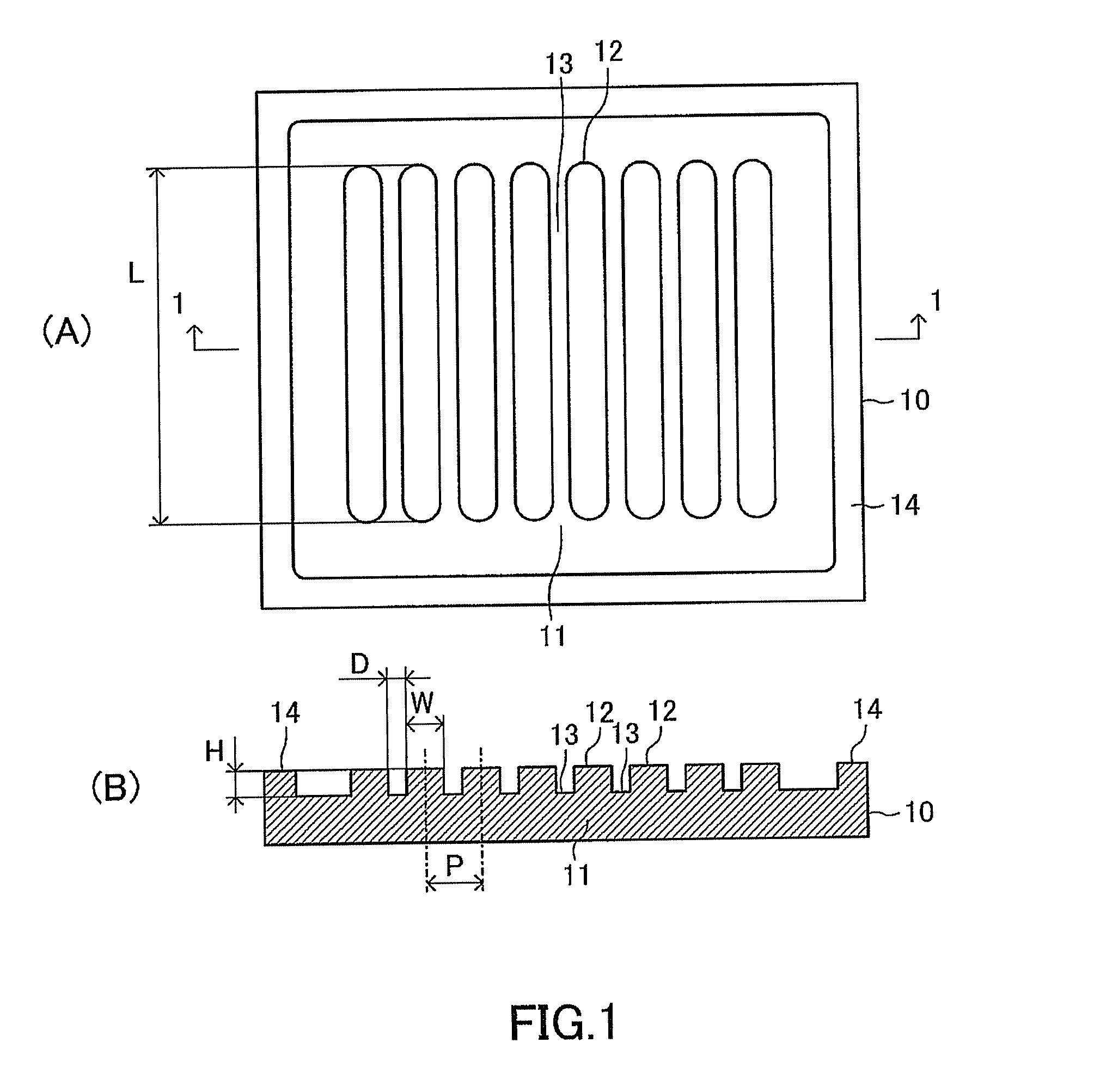
[0075]First, a mold (a pressing mold, a stamper) 10 shown in FIG. 1 is prepared. (A) of FIG. 1 is a front view of the mold 10. (B) of FIG. 1 is a cross sectional view of the mold 10 cut by a plane along a line 1-1 in (A) of FIG. 1. The mold 10 is made of a dense material such as a metal (e.g., a cemented carbide or a typical alloy). The mold 10 comprises a plurality of convex portions 12 which project or protrude from a flat plate-like base portion 11. The convex portion 12 has a substantially rectangular parallelepiped shape. The plurality of the convex portions 12 are arranged in such a manner that their longitudinal directions are parallel to each other. Accordingly, a concave portion 13 is formed between a pair of the convex portions 12, 12 which are adjacent to each other. The concave portions 13 form a pattern of “convex portions which will be eventually formed on a substrate as three dimensional forming portions”. That is, the mold 10 has “the c...

second embodiment

[0122]A method for manufacturing three dimensional forming portion according to a second embodiment of the present invention will next be described in order of steps. It should be noted that performing order of the following steps can be changed as long as there is no inconsistency.

[0123](A Mold Preparation Step)

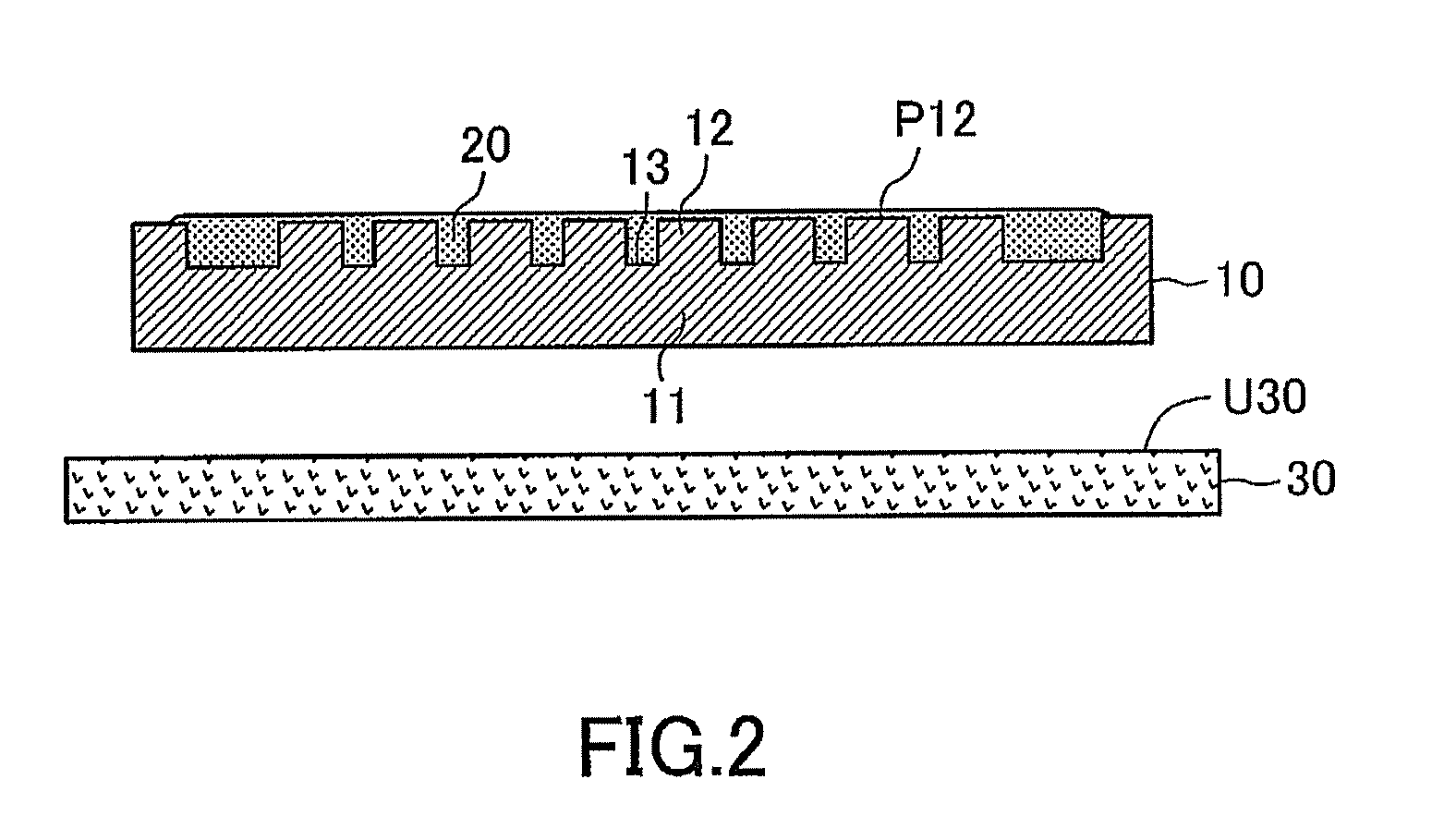
[0124]A mold 10 shown in (A) of FIG. 15 is prepared. This mold preparation step is the same as the mold preparation step described above.

[0125](A Substrate Preparation Step)

[0126]A ceramic green sheet 30 shown in (B) of FIG. 15 is prepared. This substrate preparation step is also the same as the substrate preparation step described above.

[0127](A Slurry Preparation Step)

[0128]A slurry 20 shown in (C) of FIG. 15 is prepared. This slurry preparation step is also the same as the slurry preparation step described above.

[0129](A Pre-Dried Three Dimensional Forming Portion Forming Step)

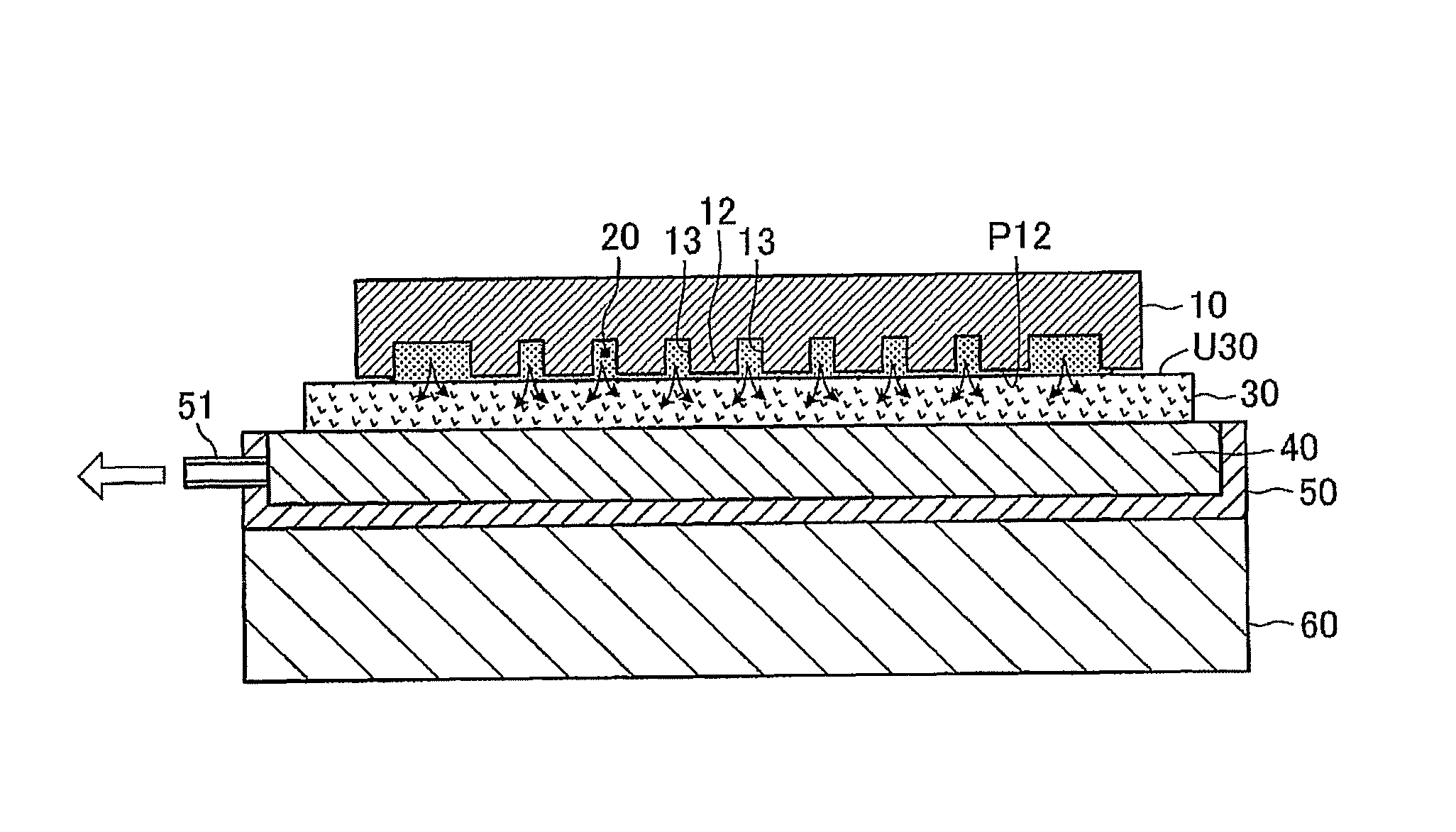
[0130]Subsequently, as shown in (C) of FIG. 15, the ceramic green sheet 30 is placed on a lower ...


PUM

PropertyMeasurementUnit
distanceaaaaaaaaaa
distanceaaaaaaaaaa
heightaaaaaaaaaa

Abstract

A mold having concave portions in a predetermined 3-D shape is prepared. A slurry is filled into the concave portions and the mold storing the slurry is then placed on an upper surface of a ceramic green sheet. A pressure inside the sheet is lowered through a pipe and a sintered porous metal support with the green sheet being heated by a hot plate. Accordingly, a solvent in the slurry is permeated into the fine pores of the green sheet and evaporated, thereby drying the 3-D forming portion without deformation.

Description

TECHNICAL FIELD OF THE INVENTION[0001]The present invention relates to a method for forming a three-dimensional forming portion having a predetermined shape, on a substrate with using “a porous substrate through which gases can pass” which, for instance, is a ceramic green sheet and the like, and a slurry including particles of a main raw material, a solvent, and an organic material.BACKGROUND OF THE INVENTION[0002]Conventionally, a ceramic laminated body having a hollow portion (a hollow space) in its inside has been widely known, the hollow portion being “a flow channel, a pressurizing chamber, and the like”. Such a ceramic laminated body is used in wide areas, serving as, for instance, “an actuator for injecting fluid” such as an actuator of an inkjet printer and a fuel injection device, a Solid Oxide Fuel Cell (SOFC), a switching device, and a sensor, etc.[0003]Typically, this kind of ceramic laminated body is manufactured through processes described below (see, for example, Jap...

Claims


Application Information

Patent Timeline
Patent Type & Authority Patents(United States)
IPC IPC(8): C03B29/00B29C65/00B29C45/14B28B1/00
CPCC04B35/111C04B35/486C04B37/001C04B2235/6027C04B2237/62C04B2235/945C04B2237/343C04B2237/348C04B2235/608B32B37/06
Inventor MASE, ATSUSHITANAKA, HIDEHIKOSHIMIZU, HIDEKI
Owner NGK INSULATORS LTD
Why Eureka
Try Eureka