Method for Reducing Runnability Problems Caused By Gas Flows in an Impingement Dryer for a Fibre Web and an Impingement Dryer

Inactive Publication Date: 2011-03-10
VALMET TECHNOLOGIES INC
View PDF4 Cites 0 Cited by
  • Summary
  • Abstract
  • Description
  • Claims
  • Application Information

AI Technical Summary

Benefits of technology

[0013]It is especially an object of the present invention to provide a solution, wherewith the runnability problems caused by air flows in an impingement dryer can be reduced.
[0054]In an embodiment of the invention indentations, located in the cross machine direction, are formed in the edge strip for reducing thermal tensions which are directed onto it. The edge strip is often substantially colder at its outer edge than at the edge toward the inner part of the dryer, which can cause large stresses to the metallic strip.

Problems solved by technology

Runnability problems typical for paper machines, caused for example by air flows, occur in impingement dryers.
This can cause edge defects in the paper web and even web breaks.
Also a too narrow blow zone, i.e. a situation, where the blowing does not extend sufficiently close to the edge of the web, can also cause the edge of the paper web to detach from the support fabric, as well as insufficient drying of the paper web at its edge areas.
The runnability problems caused by air flows are possible especially when the web and the support fabric are transported in the impingement dryer using so-called unsupported draw.
If the blow extends over the edge of the web, the support fabric may be damaged.
There is thereby a danger that the blows are not directed to the desired optimal area on the web.

Method used


Image

  • Method for Reducing Runnability Problems Caused By Gas Flows in an Impingement Dryer for a Fibre Web and an Impingement Dryer
  • Method for Reducing Runnability Problems Caused By Gas Flows in an Impingement Dryer for a Fibre Web and an Impingement Dryer
  • Method for Reducing Runnability Problems Caused By Gas Flows in an Impingement Dryer for a Fibre Web and an Impingement Dryer

Examples


Embodiment Construction

OF THE FIGURES

[0076]For the sake of clarity, the same reference number is used for some corresponding parts in different embodiments in the figures.

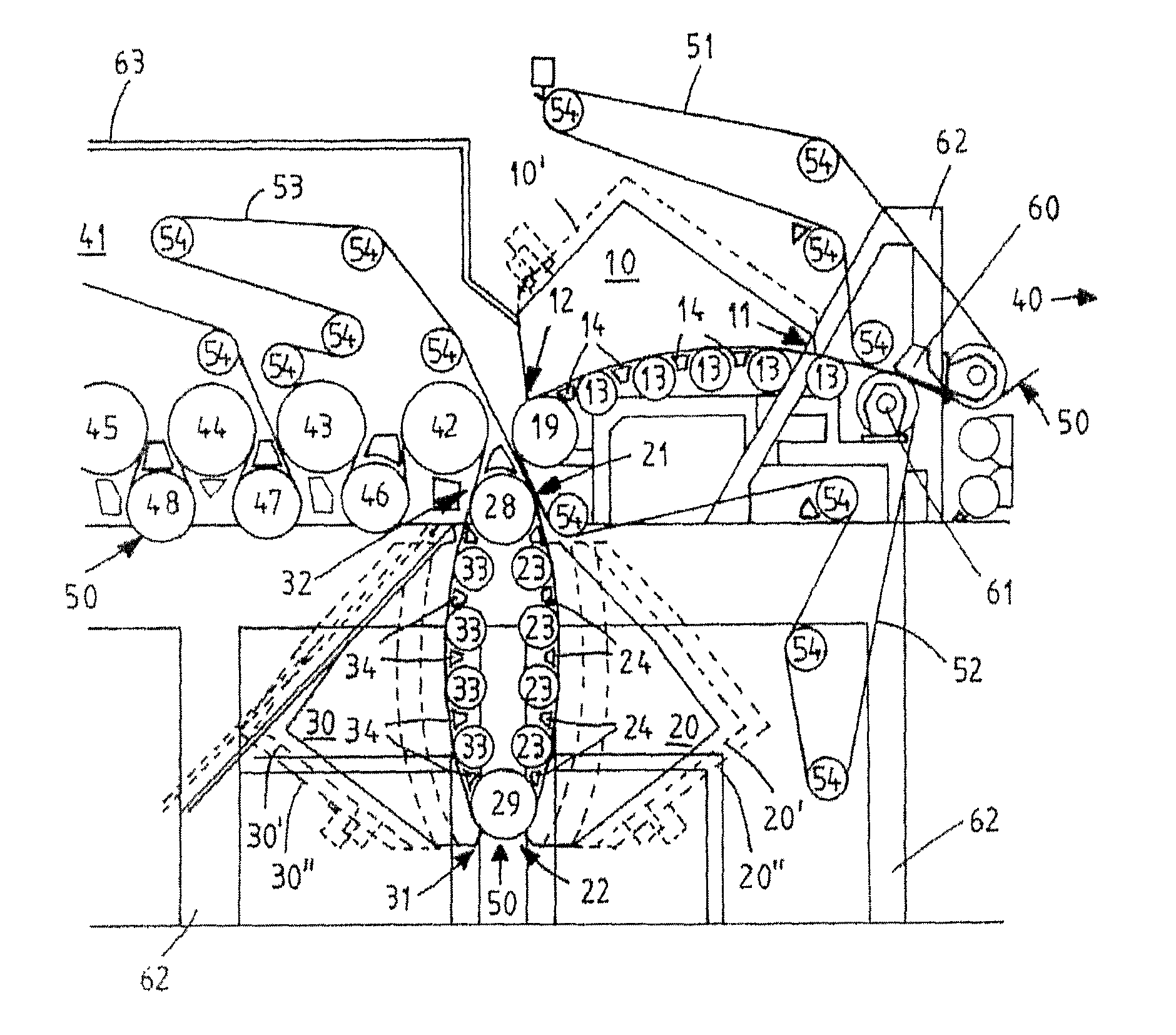
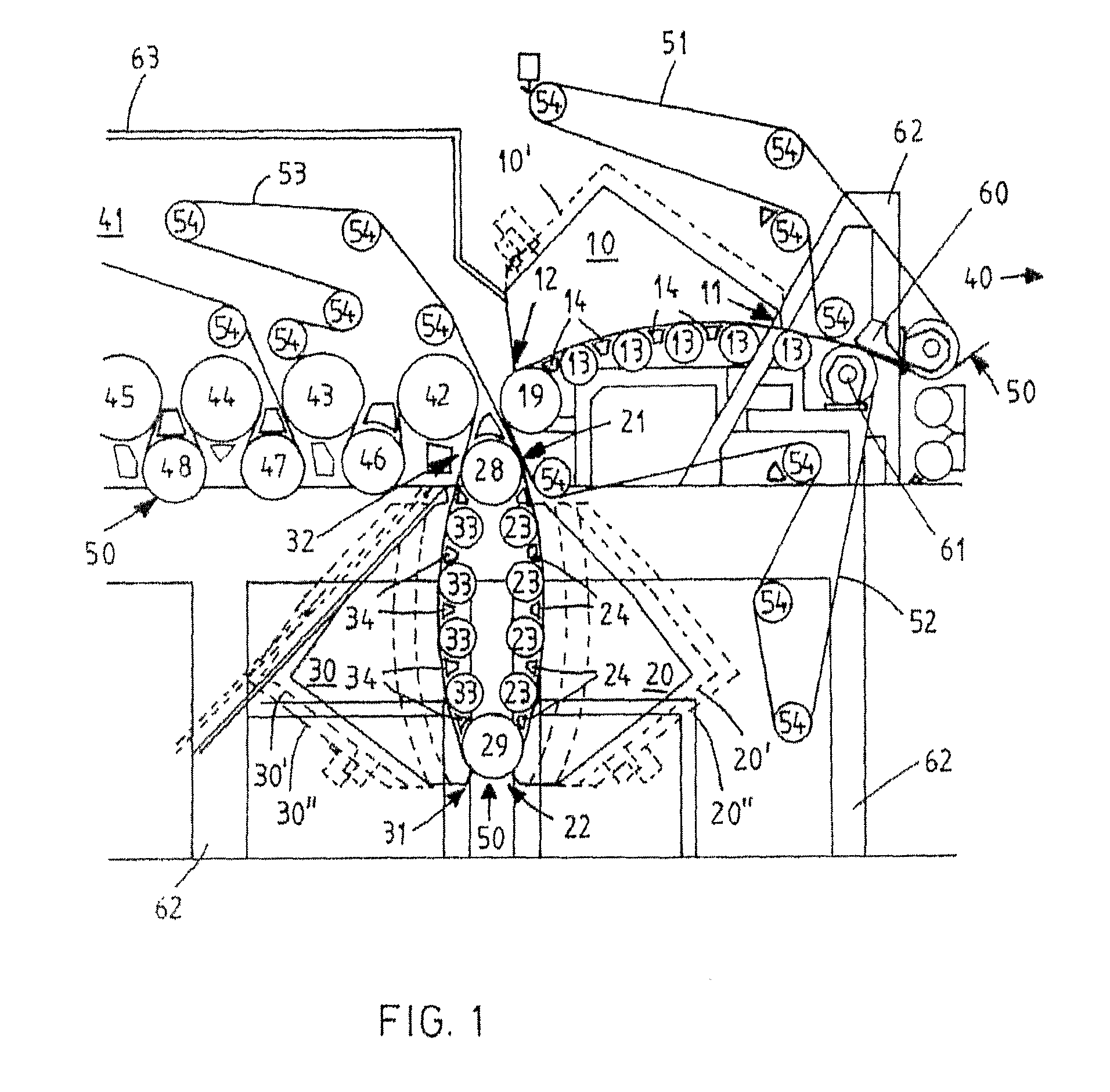
[0077]FIG. 1 show both two typical so-called vertical impingement dryers 20, 30 according to the invention and a so-called horizontal impingement dryer 10. The impingement dryers 10, 20, 30 are installed in the forward end of the drying section 41 of a paper machine, before the drying cylinders 42-45. The paper web 50 to be dried is, supported by the first wire 51, directed from the press section 40 with the aid of a runnability component 60 to the roll 61 and to be supported by the second wire 52. Thereafter the paper web 50 is, supported by the second wire 52, led in through the first end 11 of the horizontal impingement dryer 10. Inside the dryer 10 the second wire 52 and the paper web 50 travelling with it are transported substantially horizontally, supported by rotating support rolls 13 and blow boxes 14. When moving horizontally th...


PUM


Abstract

The invention relates to an impingement dryer and a method for reducing runnability problems caused by gas flows in an impingement dryer for a fibre web, which impingement dryer has gas blowing opening and gas exhaust openings. The fibre web to be dried is supported with a support fabric. The support fabric and the fibre web to be dried are moved in the machine direction inside the impingement dryer past the blowing openings and exhaust openings. At the same time hot gas is blown from the blowing openings toward the fibre web to be dried and gas is removed from the vicinity of the fibre web to the exhaust openings. At least one edge control strip is moved in the machine direction edges of the impingement dryer in front of the blowing openings or the exhaust openings or both. With its aid a desired number of blowing openings or exhaust openings or both are covered and thus their effect is controlled.

Description

CROSS REFERENCE TO RELATED APPLICATIONS[0001]This is a U.S. national stage of application No. PCT / FI2009 / 050292, filed on Apr. 20, 2009. Priority is claimed on Finland, Application No. 20080300, filed Apr. 21, 2008. The content of both applications are incorporated herein by reference.BACKGROUND OF THE INVENTION[0002]1. Field of the Invention[0003]The object of the invention is a method and an impingement dryer according to the preambles of the independent claims presented further below. The invention relates especially to a new way of arranging impingement drying for heating and drying a web travelling in the drying section of a paper machine or the like.[0004]2. Description of Prior Art[0005]An impingement dryer according to prior art comprises a web run arrangement, which supports the paper web, and a blow chamber, which on the side toward the web has blowing means for blowing air or another hot gas toward the paper web. Generally the web run arrangement comprises several subsequ...

Claims


Application Information

Patent Timeline
IPC IPC(8): F26B25/06
CPCD21F5/18D21F5/04D21F5/044
Inventor NORRI, PETRISUNDQVIST, HANS
Owner VALMET TECHNOLOGIES INC
Why Eureka
Try Eureka