
Method of and software for calculating a scatter estimate for tomographic scanning and system for tomographic scanning

a technology of tomographic scanning and scatter estimation, applied in the direction of material analysis using wave/particle radiation, instruments, nuclear engineering, etc., can solve the problems of inaccurate fit, low quality of fit, inaccurate scatter estimate, etc., and achieve the effect of improving method stability and improving fit quality

Inactive Publication Date: 2011-03-08
GENERAL ELECTRIC CO +1
View PDF0 Cites 6 Cited by
  • Summary
  • Abstract
  • Description
  • Claims
  • Application Information

AI Technical Summary

Benefits of technology

"The invention is a method for calculating a scatter estimate for a tomographic scanner to correct for scattered events in detection data. The method involves determining an estimate of unscattered events, simulating the scattered events, and fitting the detection data to these estimates using a scale factor. The invention improves the accuracy of the scatter estimate by increasing the scale factor and including a weighting scheme that takes into account the covariance of the detection data. The method can be used in a computer software system and in a tomographic scanner system. The technical effects of the invention include improved accuracy of the scatter estimate and improved image reconstruction."

Problems solved by technology

The low quality of the fit may be caused by relatively small tails and or low number of events in the tails, which can occur in whole body scans.
This may make the fit inaccurate, resulting in an inaccurate scatter estimate.
Another cause may be that the model used for making the simulation of the scatter events does not properly describe the scatter behaviour in the tails.
Due to these causes the scatter estimate in the central portion of the distribution is often inaccurate.

Method used


Image

  • Method of and software for calculating a scatter estimate for tomographic scanning and system for tomographic scanning
  • Method of and software for calculating a scatter estimate for tomographic scanning and system for tomographic scanning
  • Method of and software for calculating a scatter estimate for tomographic scanning and system for tomographic scanning

Examples


Embodiment Construction

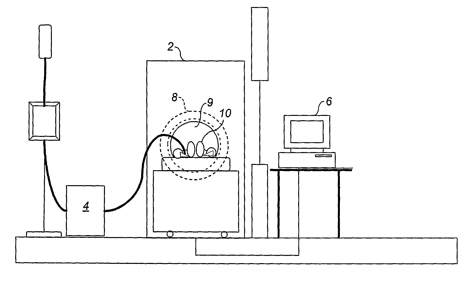
[0040]FIG. 1 shows a tomographic scanner system, arranged in accordance with an embodiment of the invention, which includes a PET scanner 2, a tracer generator module 4 and an operator computer terminal 6. The scanner 2 includes a detector array 8 arranged about a scanning area 9, in which a subject 10 is located during a transmission scan and during an emission scan.

[0041]One embodiment of the invention relates to a PET scanner, for example, a PET scanner of the so-called Discovery™ ST type (manufactured by GE Healthcare). In this embodiment, the detectors in the detector array 8 are arranged in square detector blocks, each containing multiple detector elements. The detectors blocks are arranged in multiple rings, the rings being arranged adjacent one another along a scanner axis, perpendicular to the plane of the drawing.

[0042]As shown in FIG. 2, the PET scanner 2 includes a control unit 30, processing circuitry 32 for detection data received from the detector array, a motion dete...


PUM


Abstract

The method calculates a scatter estimate for scatter correction of detection data from a subject in a positron emission tomographic scanner. The detection data represent the scattered events and unscattered events of annihilation photons emitted in the subject. The method uses the following steps:determine an estimate of the unscattered events;determine a simulation of the scattered events;determine a value of a scaling factor by fitting the sum of the estimate of the unscattered events and a product of the scaling factor and the simulation of the scattered events to the detection data; anddetermine the scatter estimate as the product of the scaling factor having said value and the simulation of the scattered events.

Description

[0001]This application is a filing under 35 U.S.C. 371 of international application number PCT / GB2007 / 004874, filed Dec. 18, 2007, which claims priority to application No. 60 / 870,421 filed Dec. 18, 2006, in The United States the entire disclosure of which is hereby incorporated by reference.FIELD OF THE INVENTION[0002]The invention relates to a method for calculating a scatter estimate for scatter correction of detection data from a subject in a tomographic scanner, the detection data representing the scattered events and unscattered events of annihilation photons emitted by the subject. The invention also relates to software carrying out the method, a data carrier comprising the computer software and a tomographic scanning system adapted for carrying out the method.BACKGROUND OF THE INVENTION[0003]A typical emission scan using a positron emission tomography (PET) scanner starts with the injection of a solution including a tracer into the subject to be scanned. The subject may be hu...

Claims


Application Information

Patent Timeline
Patent Type & Authority Patents(United States)
IPC IPC(8): G01T1/164
CPCG01T1/1647G06T11/005
Inventor THIELEMANS, KRIS FILIP JOHAN JULESTSOUMPAS, CHARALAMPOS PANOSJANSEN, FLORIBERTUS P. M. HEUKENSFELDT
Owner GENERAL ELECTRIC CO
Learn More