
Fuel cell

a fuel cell and polymer technology, applied in the field of polymer-type fuel cells, can solve the problems of deterioration of maintenance, difficult supply, and difficulty in realizing the thinner, small and lighter type of electric supply for mobile instruments, and achieve the effects of preventing short circuit between both of them, increasing thickness, and reliable sealing

Inactive Publication Date: 2011-01-04
AQUAFAIRY CORP
View PDF48 Cites 2 Cited by
  • Summary
  • Abstract
  • Description
  • Claims
  • Application Information

AI Technical Summary

Benefits of technology

This design effectively prevents hydrogen gas leakage, enables reliable sealing of each unit cell without increasing thickness, and allows for significant size reduction and weight loss, while maintaining high output and efficiency.

Problems solved by technology

However, in the prior structure as shown in FIG. 16, since a structure has no degree of freedom, it is difficult to realize a thinner, small and lighter type required as an electric supply for mobile instruments, and to make a high degree of freedom for a shape, and there is a problem of deteriorated maintenance.
Further, it is difficult to supply respectively an oxidizing gas and a reducing gas in a fuel cell without mixing them, and to make a sealed structure, and it is difficult to reduce a size and a weight of a fuel cell while satisfying these conditions.
In other words, conventionally, as cell parts have been interconnected with a securing part such as a bolt and a nut to apply a certain pressure to cell parts, it is necessary to enhance rigidity of each part in order to secure the sealing property, and thinning, miniaturization, weight reduction, and free shape design have been unavoidably difficult.
However, in the aforementioned cell structure, a force for pressing a sealing material to a side wall of a laminate containing an electrode cannot be sufficiently enhanced.
Therefore, for example, when a hydrogen gas fuel is pressurized to flow on a fuel electrode side, a hydrogen gas is leaked to an oxidizing agent electrode side, and there is a problem that such as reduction in an electric generating efficiency and risk of hydrogen combustion.

Method used


Image

  • Fuel cell
  • Fuel cell
  • Fuel cell

Examples


example 1

[0085]Twenty one grooves (width 0.8 mm, depth 0.2 mm, interval 1.6 mm) were provided on SUS (50 mm×26 mm×0.08 mm thickness) having corrosion resistance by press processing. An insulating sheet (50 mm×26 mm×2 mm width, thickness 80 μm) was then laminated to SUS. A membrane electrode assembly (49.3 mm×25.3 mm) was manufactured as described below. As a platinum catalyst, a carbon catalyst carrying 20% platinum (EC-20-PTC) manufactured by US Electrochem was used. This platinum catalyst, carbon black (Akzo; Ketchen Black EC) and polyvinylidene fluoride (Kiner) were mixed at a ratio of 75% by weight, 15% by weight, and 10% by weight, dimethylformamide was added to the mixture of a platinum catalyst, carbon black and polyvinylidene fluoride at such a ratio that a 2.5 weight % polyvinylidene fluoride solution was obtained, and the materials were dissolved and mixed in a mortar to prepare a catalyst paste. A carbon paper (TGP-H-90 manufactured by Toray Industries, Inc., thickness 370 μm) was...

example 2

[0088]According to the same manner as that of Example 1 except that SUS (50 mm×26 mm×0.3 mm thickness) having a different thickness was used, and a groove (width 0.8 mm, depth 0.2 mm, interval 1.6 mm) was formed by changing a processing method to etching with an aqueous ferric chloride solution, a thin miniature micro-fuel cell shown in FIG. 4 was obtained. In FIG. 4, a thickness of SUS at a caulking part was also reduced by etching (thickness 0.1 mm).

[0089]Cell properties of this micro-fuel cell were assessed as in Example 1. The resulting maximum output density was 450 mW / cm2 per electrode area (FIG. 13). Six fuel cells were laminated to obtain series connection, and output of 20 W as a fuel cell was obtained. The feature of the present invention is in that a cell is thin as a thickness of 1.4 mm, and a high output as 450 mW / cm2 per unit electrode area is obtained.

reference example 1

[0090]According to the same manner as that of Example 2 except that a thickness of a solid polymer electrolyte was 25 μm (½ of that of Example 2), a fuel cell was prepared. At that time, the presence or the absence of gas mixing in a cell and the presence or the absence of gas leakage to the outside of a cell were investigated in the case where a sealing member (material: fluorine resin, thickness 100 μm) having a shape shown in FIG. 10(b) was used, or not used.

[0091]As a result, when a sealing member was used, gas mixing and gas leakage did not occur at a ratio of 10 / 10, on contrast, when a sealing member was not used, gas mixing occurred at a ratio of 4 / 10, and gas leakage occurred at a ratio of 3 / 10.


PUM

PropertyMeasurementUnit
thicknessaaaaaaaaaa
thicknessaaaaaaaaaa
depthaaaaaaaaaa

Abstract

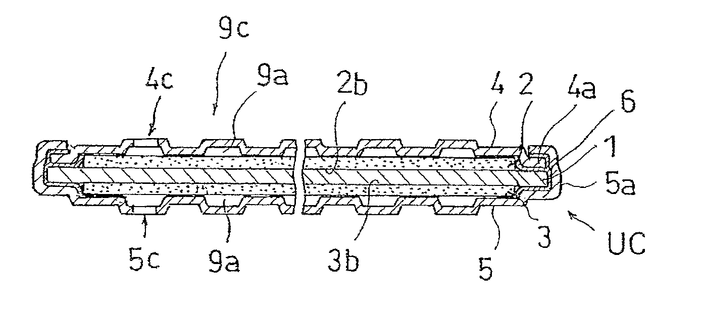
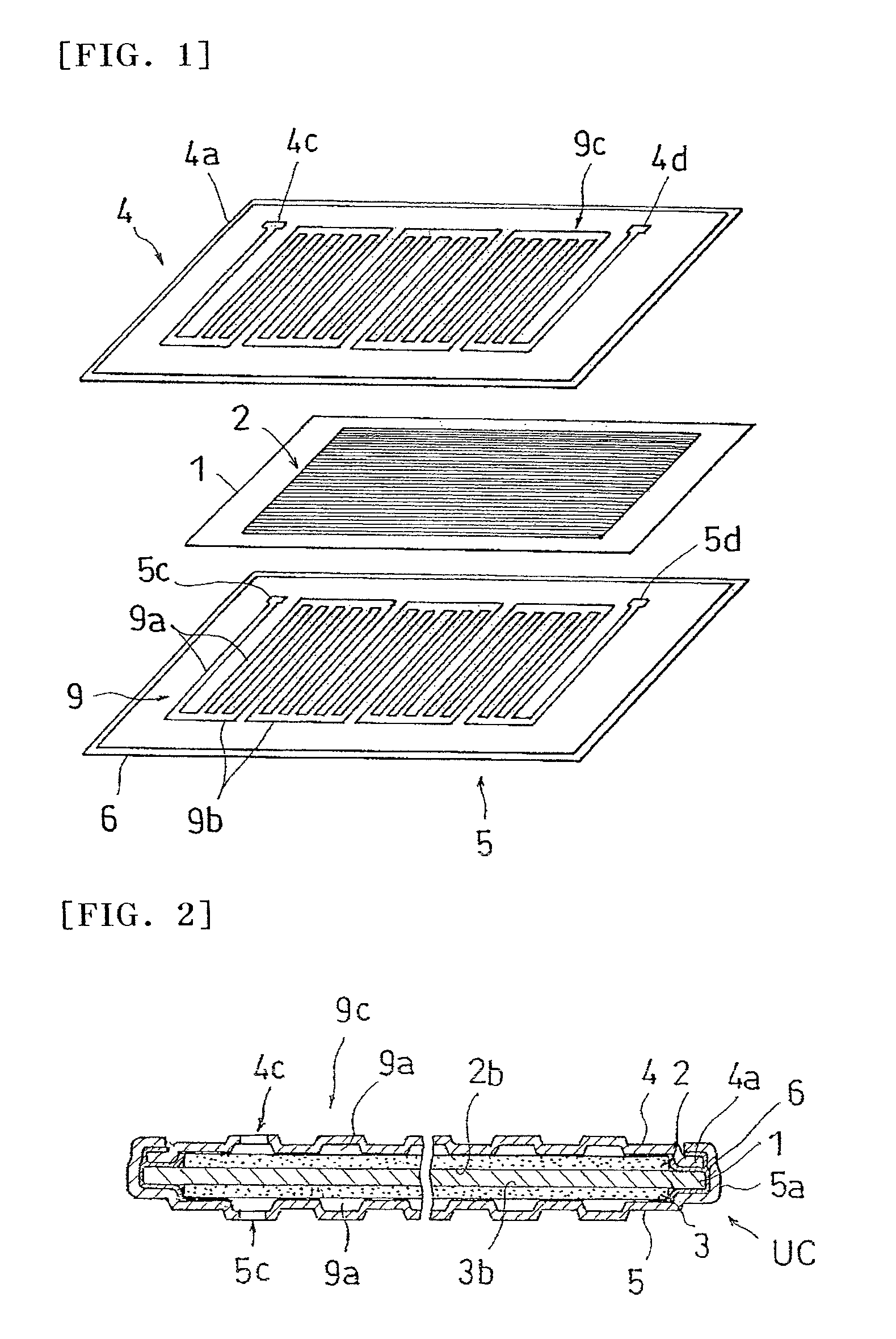
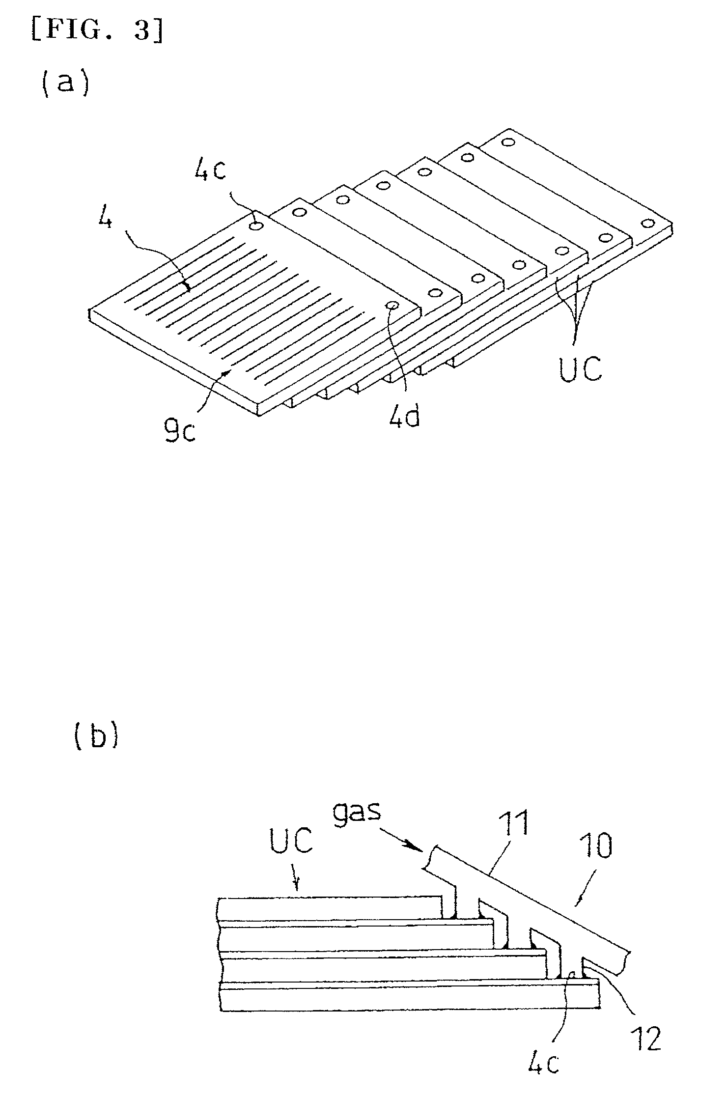
The present invention relates to and provides a fuel cell in which sealing can be reliably made for each unit cell, thereby, enabling thinning, facilitating maintenance, and enabling miniaturization and weight reduction, and enabling free shape design. A fuel cell of the present invention is characterized by comprising a sheet-like solid polymer electrolyte 1 and a pair of electrode plates 2, 3 arranged on both sides of the solid polymer electrolyte 1, and further comprising a pair of metallic plates 4, 5 arranged on both sides of the electrode plates 2, 3, and provided flow path grooves 9, and inlets 4c, 5c and outlets communicating with the flow path grooves, wherein the peripheral edges of the metallic plates 4, 5 are mechanically sealed with an insulation material 6 interposed between the metallic plates.

Description

[0001]This application is the U.S. National Phase under 35 U.S.C. §371 of International Application PCT / JP2004 / 016953, filed Nov. 15, 2004, which claims priority to Japanese Patent Application No. 2003-389053, filed Nov. 19, 2003, No. 2003-389059, filed Nov. 19, 2003, No. 2004-035304, filed Feb. 12, 2004, No. 2004-118083, filed Apr. 13, 2004, and No. 2004-163116, filed Jun. 1, 2004. The International Application was not published under PCT Article 21(2) in English.TECHNICAL FIELD[0002]The present invention relates to a fuel cell using a solid polymer electrolyte, more particularly, it relates to a polymer-type fuel cell which can reduce a thickness.BACKGROUND ART[0003]Since a polymer-type fuel cell using a solid polymer electrolyte such as a polymer electrolyte has a high energy conversion efficiency, and is a thin and small type, and is light, it has been actively developed for a home cogeneration system and a motorcar. As a structure of the prior art of such the fuel cell, a struc...

Claims


Application Information

Patent Timeline
Patent Type & Authority Patents(United States)
IPC IPC(8): H01M2/08H01M2/00H01M2/02H01M8/02H01M8/10
CPCH01M8/023H01M8/0276H01M8/028H01M8/0286H01M8/0206H01M8/026H01M8/0263H01M2008/1095H01M2250/30Y02E60/50Y02B90/18H01M8/0273Y02B90/10H01M8/02H01M8/10
Inventor YANO, MASAYASUGIMOTO, MASAKAZUOKEYUI, TAKUJIARAKI, TOSHIO
Owner AQUAFAIRY CORP
Learn More