
Cushion for a respiratory mask assembly

a technology of respiratory mask and clamping plate, which is applied in the direction of breathing mask, heat protection, breathing protection, etc., can solve the problems of excessive force applied to obtain a seal, discomfort and possibly skin irritation, and sores on the face of patients, so as to achieve more comfort for patients

Active Publication Date: 2009-04-28
RESMED LTD
View PDF36 Cites 279 Cited by
  • Summary
  • Abstract
  • Description
  • Claims
  • Application Information

AI Technical Summary

Benefits of technology

[0017]One aspect of the invention is directed towards a mask assembly having a cushion that provides more comfort to the patient.
[0027]Another aspect of the invention is to provide an elastic cuff to the cushion. The elastic cuff may have a modulus of elasticity which is greater than a modulus of elasticity of the remaining portions of the cushion, such that it may vary more easily deform or stretch in response to localized pressure and / or force changes between the mask and the wearer's face, thereby avoiding a compromise in the seal during movement of the patient. The elastic cuff may be formed in one piece with the cushion, along an intermediate portion of the cushion between the contacting and non-contacting portions of the cushion. The elastic cuff may also be formed separate from the cushion and assembled to the contacting and / or non-contacting portions of the cushion.
[0029]An additional aspect of embodiments of the invention provides a full face mask that effectively seals the region directly below and / or to the sides of the lower lip.
[0030]A further aspect of embodiments of the invention provides a full face mask that offers effective sealing at relatively high pressures.

Problems solved by technology

A common problem with prior art mask assemblies, such as the mask assemblies taught by U.S. Pat. Nos. 5,074,297, 5,243,971 and 6,112,746 and PCT Patent Application AU01 / 00746, is patient comfort.
Patients can develop sores and red marks on their faces after several hours use of a mask assembly.
Moreover, the face contacting portion may apply excessive pressure to the wearer's face resulting in discomfort and possibly skin irritation.
This can occur when the face contacting portion is distorted beyond its normal range of elasticity to conform to certain facial contours, thus requiring the application of excessive forces to obtain a seal.
In some cases, these excessive pressures and forces may cause the wearer's face to distort to conform with the face contacting portion, which increases wearer discomfort, facial soreness and ulceration.
Another common problem with prior art mask assemblies is buildup of CO2 in the mask cavity.
Another common problem with these masks is a broken or ineffective seal. for example, the mask may become dislodged if the wearer rolls over when sleeping, thereby creating a drag force on the gas supply line which is transmitted to the mask and breaking the seal between the mask and wearer.
If a mask is used for the administration of Continuous Positive Airway Pressure (CPAP) treatment for the condition obstructive sleep apnea, such a leak can result in a pressure supplied to the entrance of the wearer's airway that is below the therapeutic value.
Thus, treatment becomes ineffective.
Another problem with mask assemblies which include a gusset section is visual size, both perceived and actual.
Another problem with existing full face masks occurs when wearers move their jaws during treatment, which often happens.
As a result, air leaks are created below the mouth from the mid-region extending to the region at the sides or corners of the mouth.

Method used


Image

  • Cushion for a respiratory mask assembly
  • Cushion for a respiratory mask assembly
  • Cushion for a respiratory mask assembly

Examples


Embodiment Construction

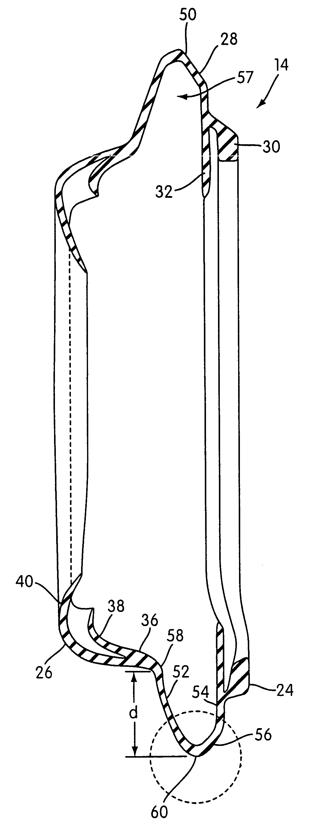
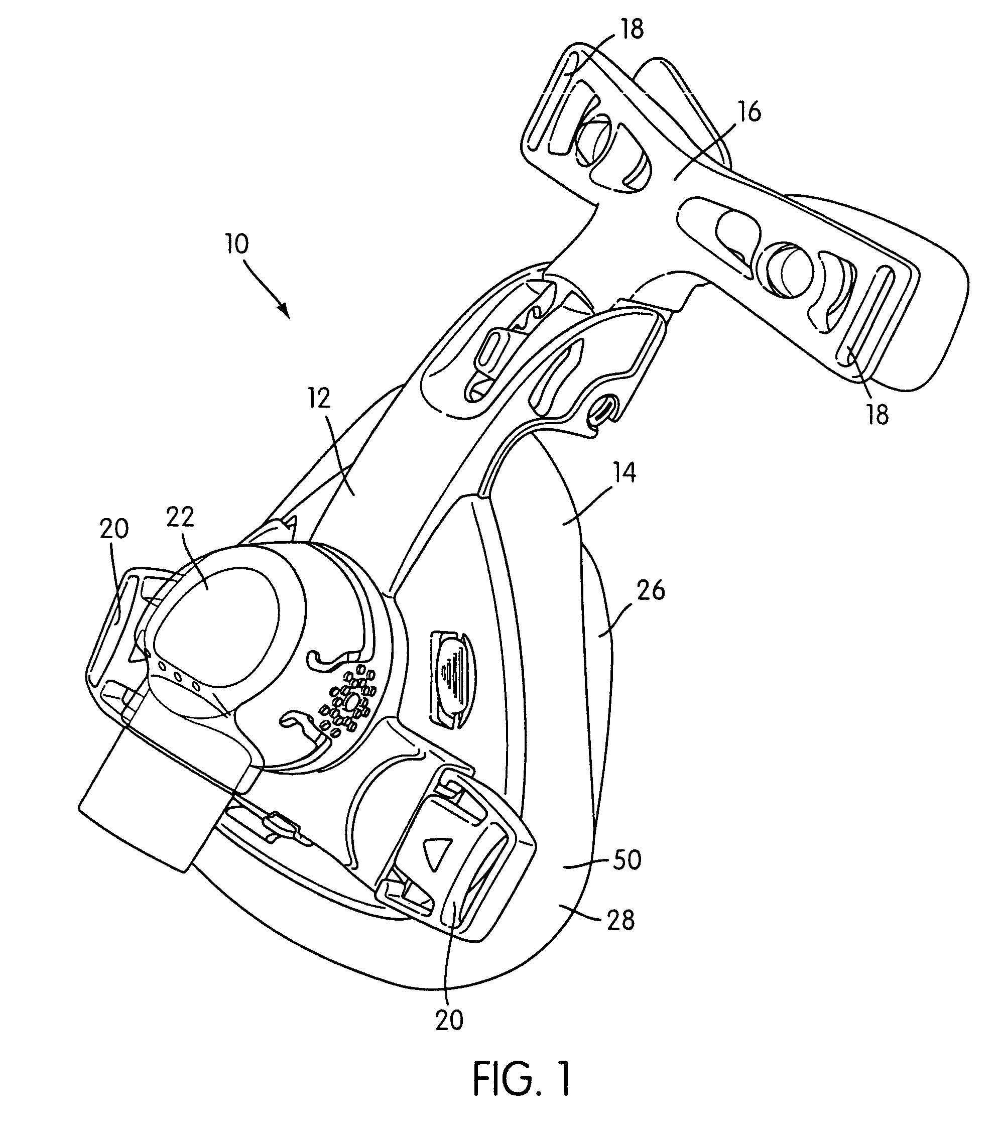
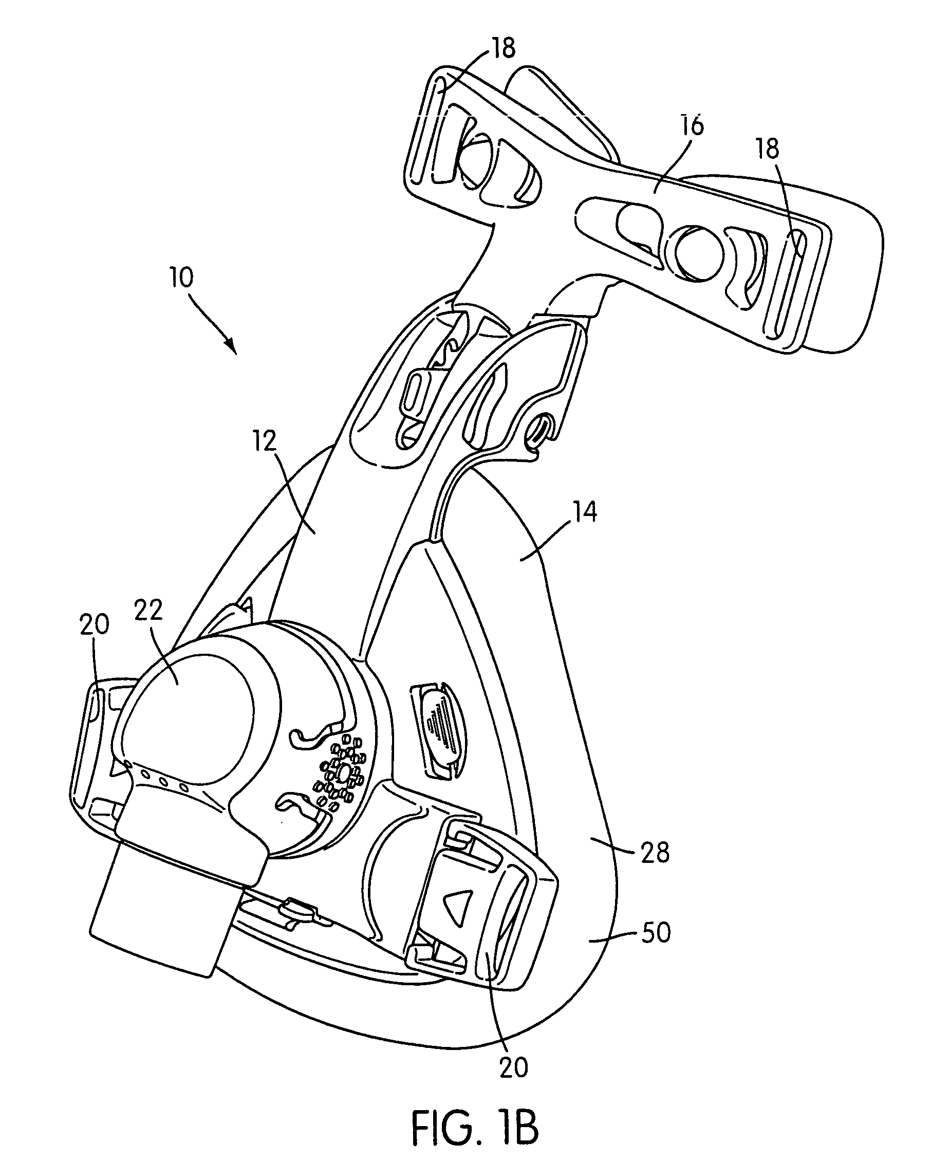
[0111]FIGS. 1-5B show a respiratory mask assembly 10 that includes a frame 12 and a cushion 14 that may be permanently or removably connected to the frame 12. A forehead support 16 is movably mounted to an upper portion of the frame 12. A headgear assembly (not shown) can be removably attached to the frame 12 to maintain the frame 12 and cushion 14 in a desired adjusted position on the patient's face. For example, the headgear assembly may include a pair of upper and lower straps with the upper straps removably connected to clip structures 18 provided on the forehead support 16 and the lower straps removably connected to clip structures 20 provided on the frame 12. However, the headgear assembly and frame 12 may be removably attached to one another in any suitable manner.

[0112]In the illustrated embodiment, the mask assembly 10 is a nasal mask structured to deliver breathable gas to a patient's nose. However, the mask assembly 10 may be nasal and mouth mask or the mask assembly may ...


PUM

PropertyMeasurementUnit
widthaaaaaaaaaa
widthaaaaaaaaaa
widthaaaaaaaaaa

Abstract

A respiratory mark assembly for delivering breathable gas to a patient includes a frame and a cushion. The cushion has a non-face contacting portion structured to be connected to the frame, a face-contacting portion structured to engage the patient's face, and an intermediate portion that interconnects the non-face contacting portion and the face-contacting portion. The intermediate portion includes a gusset portion that applies a first component of force to the patient's face through the face-contacting portion. A spring structure is coupled with the face-contacting portion of the cushion. The spring structure applies a second component of force to the patient's face through the face-contacting portion. The first and second components of force applied by the gusset portion and spring structure, respectively, determine a contact force of the cushion applied to the patient's face through the face-contacting portion. The intermediate portion may also include an elastic cuff portion. Further, in the case of an oral mask, the sealing section may include a portion that is designed to promote a better seal in the chin region of the mask.

Description

CROSS REFERENCE TO PRIORITY APPLICATIONS[0001]This application claims the benefit of U.S. Provisional Application No. 60 / 424,686 filed Nov. 8, 2002, U.S. Provisional Application No. 60 / 483,622 filed Jul. 1, 2003, and the present application is a Continuation-In-Part of U.S. Non-Provisional application Ser. No. 10 / 235,846 filed Sep. 6, 2002, now U.S. Pat. No. 6,823,869 which in turn claims priority to U.S. Provisional Application No. 60 / 317,486 filed Sep. 7, 2001 and U.S. Provisional Application No. 60 / 342,854 filed Dec. 28, 2001. Each of the above identified applications is incorporated herein by reference in its entirety.FIELD OF THE INVENTION[0002]The present invention relates to a cushion for a respiratory mask assembly used for providing ventilatory support, e.g., for treatment of Sleep Disordered Breathing (SDB) with Non-invasive Positive Pressure Ventilation (NPPV).BACKGROUND OF THE INVENTION[0003]The use of NPPV for treatment of SDB such as Obstructive Sleep Apnea (OSA) was p...

Claims


Application Information

Patent Timeline
Patent Type & Authority Patents(United States)
IPC IPC(8): A62B18/08A61M16/06A61M16/08
CPCA61M16/06A61M16/0683A61M16/08A61M16/0825A61M16/0616A61M16/0622A61M16/0633A61M16/0638A61M16/0611Y10T29/4987
Inventor LITHGOW, PERRY DAVIDFRATER, ROBERT HENRYDREW, JOANNE ELIZABETHGUNEY, MEMDUHFU, TIMOTHY TSUN-FAIKWOK, PHILIP RODNEYDARKIN, DONALD
Owner RESMED LTD
Learn More