
Polymeric foam tube insulations and method for continuously producing such a tube

a technology of polymeric foam and pipe insulation, which is applied in the direction of rigid pipes, coatings, flexible pipes, etc., can solve the problems of limited service temperature, low thermal conductivity, and poor thermal resistance of polymeric foam, so as to improve thermal resistance and thermal conductivity

Inactive Publication Date: 2010-12-21
ARMACELL ENTERPRISE GMBH
View PDF16 Cites 3 Cited by
  • Summary
  • Abstract
  • Description
  • Claims
  • Application Information

AI Technical Summary

Benefits of technology

[0012]It is the object of the invention to provide a preferably continuously produced polymeric foam tube for pipe insulations having an improved thermal resistance and thermal conductivity and being able to take up pipe insulations within a predetermined range of outer diameters.
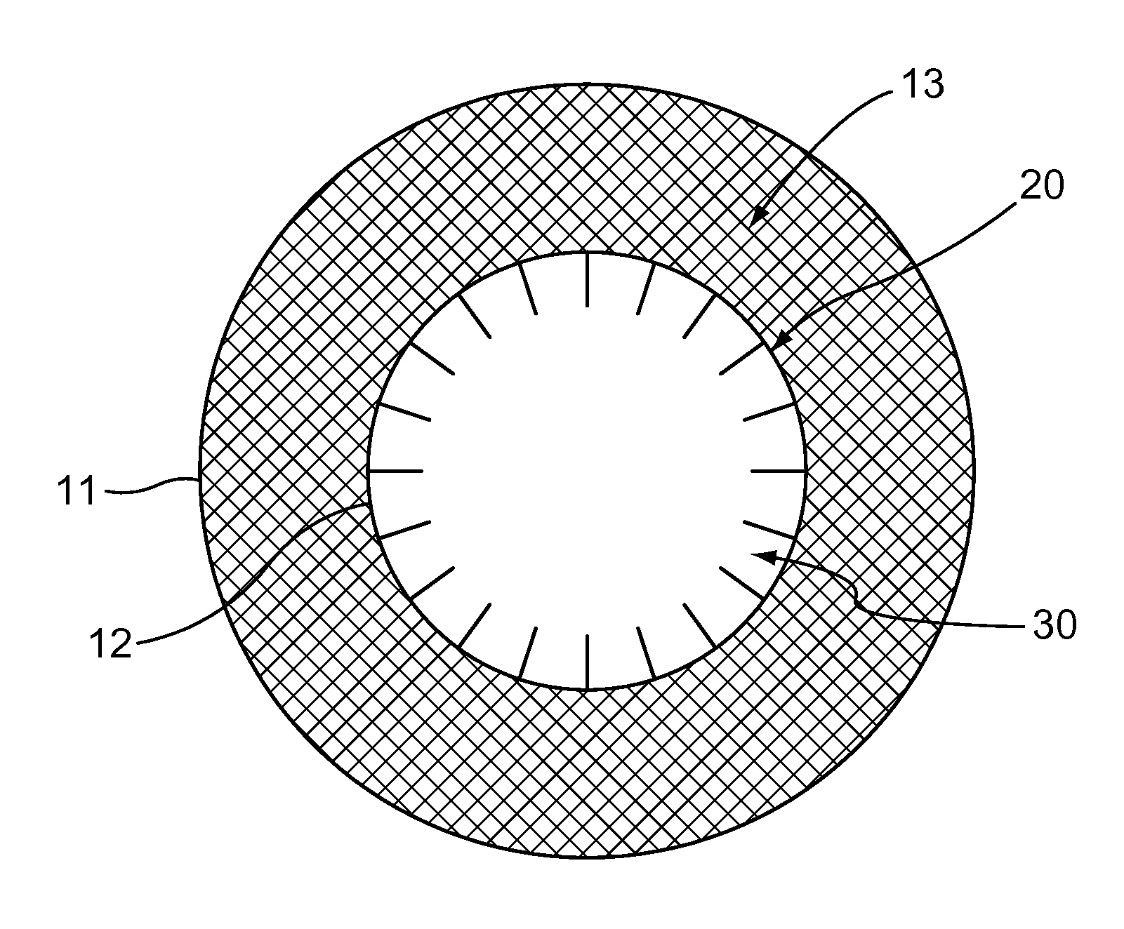
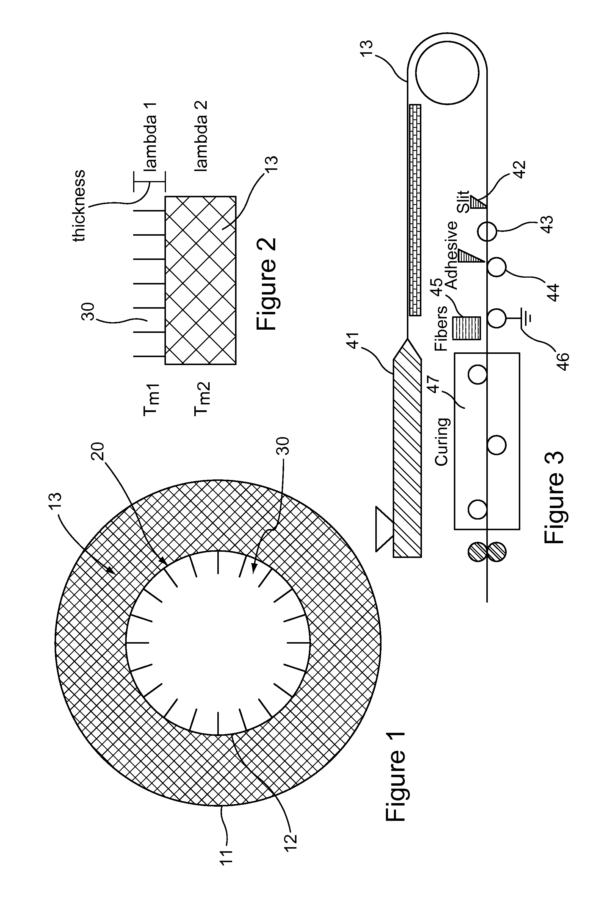
[0020]As the surface of the tube is only partially covered with the fibers, the inner layer is mostly air. The thermal conductivity of this layer is below that of the insulation tube, hence decreasing the thermal conductivity value of the insulation tube. Furthermore, since the small fibers are made of a material, preferably polymeric, having a high melt temperature, and the thermal conductivity being low, the service temperature is significantly increased from that of the general insulation foam.

Problems solved by technology

One of the drawbacks of polymeric foams is the thermal resistance of it.
Typically all foams collapse close to the melting point of the matrix polymer, and therefore they are very limited in terms of service temperature.
A low thermal conductivity on the other hand is not an easy task, since the thermal conductivities of typical materials are much higher than desired.

Method used


Image

  • Polymeric foam tube insulations and method for continuously producing such a tube
  • Polymeric foam tube insulations and method for continuously producing such a tube

Examples


example

[0035]A polyethylene tube having an internal diameter of 34 mm and a wall thickness of 10 mm is extruded using isobutene as a physical blowing agent. The product is cooled for one minute prior to on-line slitting (42), after which an adhesive is applied (44) using a specially designed die used for coatings. Immediately after applying (44) the adhesive, polyamide fibers of 22 dtex and 3 mm in length are electrostatically charged (45) using a suitable equipment. After curing of the adhesive the final step of the process, closing the tube, will be made using 350° C. hot-air nozzles to fuse the two sides back together. The final product, an internally fiber covered tube having an internal diameter of 28 mm and a wall thickness of 13 mm, with improved temperature resistance and thermal conductivity is packed in two meter tube pieces.


PUM

PropertyMeasurementUnit
Lengthaaaaaaaaaa
Fractionaaaaaaaaaa
Fractionaaaaaaaaaa

Abstract

The foam tube for pipe insulations has an external surface and an internal surface. The internal surface is provided with an adhesively bonded layer of fibers. The fibers are a material having a melt temperature that is higher than that of the polymeric foam. The fibers are adhesively bonded to the internal surface such as to stand up from the internal surface. The fibers are substantially uniformly distributed over the internal surface providing a surface coverage of 2 to 20 percent. Further, the fibers have a linear density of 0.5 to 25 dtex and a length of 0.2 to 5 mm. With this fiber layer the polymeric foam tube has an improved thermal resistance and thermal conductivity.

Description

CROSS-REFERENCE TO RELATED APPLICATION[0001]This application is a National Phase of International Application Serial No. PCT / EP2003 / 007814, filed Jul. 18, 2003.BACKGROUND OF THE INVENTION[0002]1. Field of the Invention[0003]The invention relates to polymeric foam tube for pipe insulations, wherein the tube has an external surface and internal surface the latter being provided with an adhesively bonded additional layer.[0004]2. Description of the Background Art[0005]The invention further relates to a method for continuously producing a polymeric foam tube for pipe insulations, wherein the polymeric foam tube is extruded providing an external and an internal surface, the extruded tube is axially slit from its external surface to its internal surface, the slit tube is spread to the shape of a plate, an adhesive layer is applied to the exposed internal surface of the tube spread to the shape of a plate, an additional layer is applied to the adhesive layer and bonded thereto, and the spr...

Claims


Application Information

Patent Timeline
IPC IPC(8): F16L9/14B05D1/16B29C44/56F16L59/02
CPCB05D1/16B29C44/56F16L59/021
Inventor MELLER, MIKAWEIBEL, JUERGDAVIS, STEPHEN C.WHITE, SCOTT A.PRINCELL, CHARLES
Owner ARMACELL ENTERPRISE GMBH
Learn More