Current mode logic multi-tap feed-forward equalizer

a feed-forward equalizer and current mode technology, applied in the field of physical layer (phy) communication circuitry, can solve the problems of degrading the received signal, difficult to control the delay elements, and type of ffe circuitry having the disadvantage of consuming power

Active Publication Date: 2010-12-07
MACOM CONNECTIVITY SOLUTIONS LLC
View PDF4 Cites 5 Cited by
  • Summary
  • Abstract
  • Description
  • Claims
  • Application Information

AI Technical Summary

Problems solved by technology

Significant inter-symbol interference (ISI) may occur that degrades the received signal and causes errors, in the receiving data due to the dispersive behavior the channel from skin effect of metal, dielectric loss, cross-talk, and reflection due to impedance mismatches.
In high speed data transmission, this type of FFE circuitry has the disadvantage of consuming power.
It is difficult to control the delay elements, especially when more stage / taps are needed to compensate multiple post-cursor ISI.
Another disadvantage is that this type of FFE cannot compensate for pre-cursor ISI.
XOR gates in the high speed signal path degrade the signal and add jitter to the data.
Also, simple coefficient control differential circuits may not provide the right signal level and shape for optimal performance.

Method used


Image

  • Current mode logic multi-tap feed-forward equalizer
  • Current mode logic multi-tap feed-forward equalizer
  • Current mode logic multi-tap feed-forward equalizer

Examples


Embodiment Construction

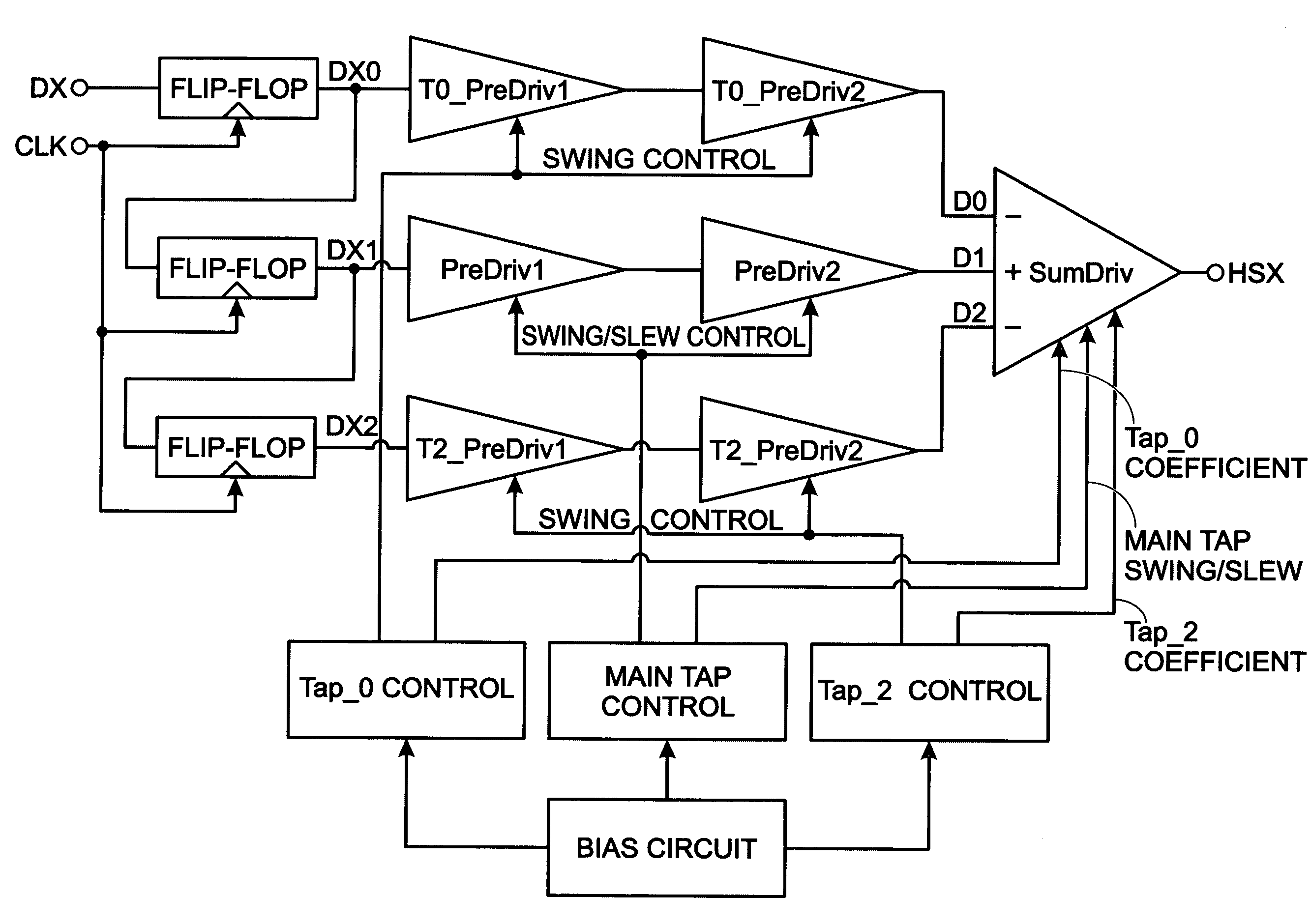
[0025]FIG. 4 is a schematic block diagram of a transmitter 300 with a system for feed-forward equalization. The system 302 comprises a temporal circuit 304 having an input on line 306 to accept a serial stream of input digital data signals, and outputs on line 308 to supply a temporal sequence of signals for each input data signal. Here, n represents the number of signals in a temporal sequence.

[0026]FIG. 5 is a diagram depicting a temporal sequence of signals associated with three consecutively received input data signals. A temporal sequence of signals is a presentation of an input signal with multiple delayed representations. For example, an input digital “1” value can be represented as a series of “1” values, where each “1” value is delayed from the next by one clock cycle. Although the temporal series is shown as consisting of 5 values in this example, the invention is not limited to any particular value. For simplicity, each of the three consecutive input data signals is shown...


PUM


Abstract

A system and method are provided for feed-forward equalization (FFE) in a transmission system. The method accepts a serial stream of input digital data signals. For each input data signal, a temporal sequence of signals is generated. Each of the signals in the temporal sequence is selectively shaped. Shaping map include varying the degree of amplification, modifying the slew rate, or varying the time delay. The contributions of the selectively shaped signals in the temporal sequence are then selectively weighted, and a summed output signal is transmitted.

Description

BACKGROUND OF THE INVENTION[0001]1. Field of the Invention[0002]This invention generally relates to physical layer (PHY) communication circuitry and, more particularly, to a system and method for using a current mode logic (CML) summing amplifier with multiple taps as feed-forward equalizer (FFE) in high speed data transmission to compensate for losses in the transmission medium.[0003]2. Description of the Related Art[0004]FIG. 1 is a diagram illustrating a high speed data transmission system (prior art). The data channel may be a printed circuit board (PCB) trace and include connectors and vias on the PCB board, or a length of transmission line to connect a receiver. Significant inter-symbol interference (ISI) may occur that degrades the received signal and causes errors, in the receiving data due to the dispersive behavior the channel from skin effect of metal, dielectric loss, cross-talk, and reflection due to impedance mismatches. A feed forward equalizer (FFE) and / or a decision...

Claims


Application Information

Patent Timeline
Patent Type & Authority Patents(United States)
IPC IPC(8): H03K5/159H03H7/40H03H7/30
CPCH04L25/028H04L25/03343
Inventor AN, HONGMINGFU, WEIMERRILL, ALLENCONROY, KEITH MICHAEL
Owner MACOM CONNECTIVITY SOLUTIONS LLC
Why Eureka
Try Eureka