
System to continuously produce carbon fiber via microwave assisted plasma processing

Active Publication Date: 2010-11-02
UT BATTELLE LLC
View PDF14 Cites 43 Cited by
  • Summary
  • Abstract
  • Description
  • Claims
  • Application Information

AI Technical Summary

Benefits of technology

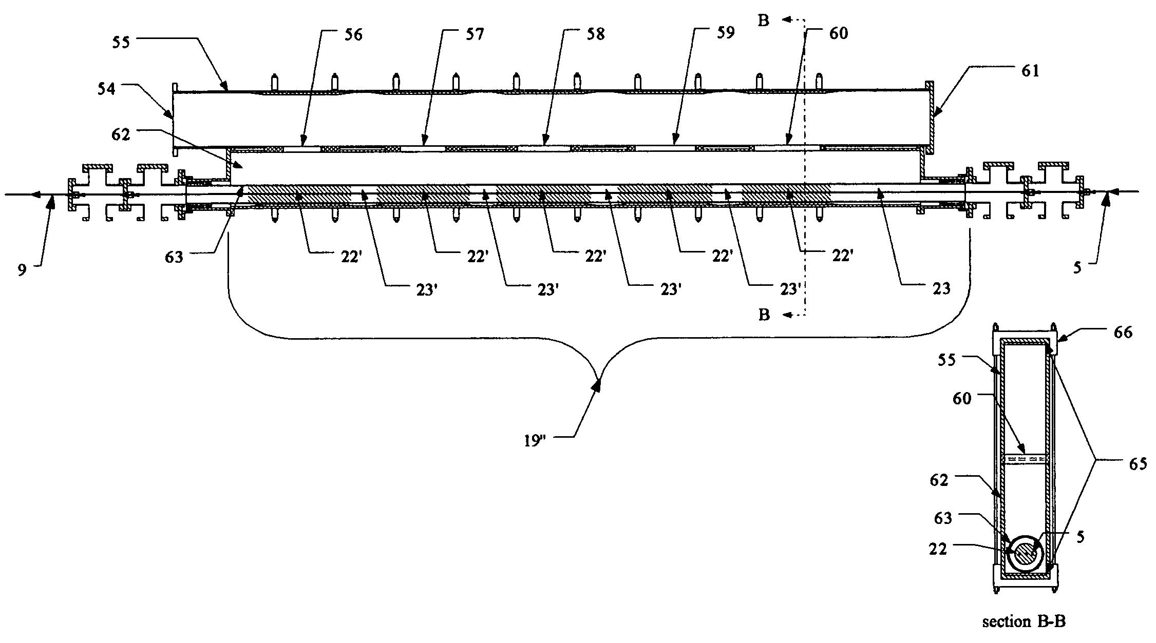
[0018]Objects of the present invention include the following: providing an apparatus for continuously processing carbon fiber; providing an apparatus for subjecting carbon fiber to a microwave plasma; providing an apparatus for transporting a carbon fiber tow through a microwave plasma chamber while controlling the flow of gases into or out of the chamber; providing an apparatus for producing carbon fiber at lower cost and with improved properties; providing an apparatus for producing carbon fiber while reducing the amount of effluent gases that must be scrubbed; providing a method for making fully carbonized or graphitized carbon fibers using microwave assisted plasma processing; providing a method for carbonizing or graphitizing a fiber tow at higher speed and lower cost; and, providing a method for maintaining a selected plasma processing environment while transporting a fiber tow continuously through said environment. These and other objects and advantages of the invention will become apparent from consideration of the following spe

Problems solved by technology

The most significant obstacle to the widespread use of high-strength, light-weight, carbon fiber based composites by the consumer industry is the high cost of carbon fibers in comparison to lower-strength but heavier conventional structural materials such as steel.
This has limited the application of carbon fibers to reinforcing materials in advanced polymer matrix composites.
Although this number may seem substantial, the commercial industry has yet to realize the potential widespread use of carbon fibers because of the high costs associated with their production as compared to other materials.
The most significant cost factors include the high cost of carbon precursors (45-50% of production costs), the high cost of equipment and energy consumption (20-25% of production costs), and the cost associated with a limited production rate for a quality product.
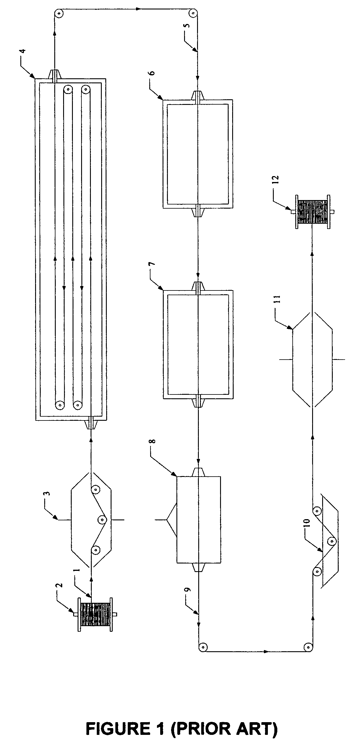
Carbon and graphite fibers are conventionally produced through the controlled pyrolysis of fibrous organic carbon precursors such as PAN, mesophase pitch (petroleum or coal tar), rayon or other polymeric based precursor in what is generally a lengthy and expensive process.
The carbonization process is time consuming and expensive because of power requirements and furnace maintenance costs.
Attempts to speed the carbonization process can produce volatile gases such as carbon monoxide and hydrogen, which can create bubbles or cracks in the filaments depending upon quality of precursor and stabilization recipes.
These bubbles are structural flaws that substantially weaken the fibers.
In the case of PAN, approximately half of the weight of the tow is lost during the carbonization stage.
Some of these gaseous components are hazardous, so these gases are usually passed through a conventional scrubbed incinerator.
The required incineration of the effluents of carbon fiber production adds manufacturing costs that must be passed along to the customer.
Incinerators must operate within their required permitting range and this represents a regulatory limitation on the quantity of carbon fiber production at a given plant.
Unfortunately, a small gap operating at very high electric fields is very prone to dielectric breakdown in the air gap between the electrodes.
This would not be very reliable in a production environment.
Another problem with the system of '062 is that carbon fiber quickly becomes highly electrically conductive as it is processed from fully carbonized to fully graphitized.
However, the electric fields in the small gap can be easily shorted out because the filament begins to conduct as it is heated and this would limit dielectric heating and would tend to cause high voltage breakdown in the gap.
Processing the filament with such a system would be very delicate because the carbon fiber filament needs to exit the high field gap before it can cause breakdown, but if the filament residence time is too short, the filament never is fully processed.
The heating process would tend to be self-limiting and not very reliable because of electric field breakdown.
The process is inherently a systematic batch process not suitable for continuous processing applications.
The process is primarily a laboratory technique and was not specifically adapted to the continuous manufacture of carbon fiber.
This method is not suitable for producing carbon fibers on an industrial scale.
The applications uses a non-thermal capillary discharge plasma that is, in general, not very uniform over a large processing area.
This method limits itself to the application of plasma with chemical feedstocks, such as hydrocarbons, to chemically oxidize or to produce functional chemical groups on the processed material.

Method used


Image

  • System to continuously produce carbon fiber via microwave assisted plasma processing
  • System to continuously produce carbon fiber via microwave assisted plasma processing
  • System to continuously produce carbon fiber via microwave assisted plasma processing

Examples


example

[0068]X-Ray Photoelectron Spectroscopy (XPS) analysis of carbon fiber produced in the MAP system with a small air leakage demonstrated a concentration of surface oxygen equal or higher than the corresponding values present on a conventionally-produced carbon fiber with standard industrial ozone surface treatment. XPS analysis was performed with a large aperture 0.8 mm and a minimum of 25 sweeps for each data point. Table 3 shows that the MAP processed fibers with a small amount of oxygen has higher amounts of elementary oxygen on the surface of the fibers compared to conventional carbon fibers.

[0069]

TABLE 3Surface oxygen content on fibersMeasuredStandardFiber SamplesPositionsAverage (%)Deviation (%)MAP 1118.01.9MAP 257.51.8MAP 357.12.5MAP 459.22.1Untreated Conventional2-4Ozone-Treated4.7-5.8Conventional

[0070]This surprising effect of the basic MAP system creates added benefits because this system can process fibers from a state of fully-oxidized precursor all the way to surface-trea...


PUM

PropertyMeasurementUnit
Pressureaaaaaaaaaa
Fractionaaaaaaaaaa
Fractionaaaaaaaaaa

Abstract

A system to continuously produce fully carbonized or graphitized carbon fibers using microwave-assisted plasma (MAP) processing comprises an elongated chamber in which a microwave plasma is excited in a selected gas atmosphere. Fiber is drawn continuously through the chamber, entering and exiting through openings designed to minimize in-leakage of air. There is a gradient of microwave power within the chamber with generally higher power near where the fiber exits and lower power near where the fiber enters. Polyacrylonitrile (PAN), pitch, or any other suitable organic / polymeric precursor fibers can be used as a feedstock for the inventive system. Oxidized or partially oxidized PAN or pitch or other polymeric fiber precursors are run continuously through a MAP reactor in an inert, non-oxidizing atmosphere to heat the fibers, drive off the unwanted elements such as oxygen, nitrogen, and hydrogen, and produce carbon or graphite fibers faster than conventionally produced carbon fibers.

Description

STATEMENT REGARDING FEDERALLY SPONSORED RESEARCH[0001]This invention was made with Government support under Contract No. DE-AC05-00OR22725 awarded by the U.S. Department of Energy to UT-Battelle, LLC, and the Government has certain rights in this invention.BACKGROUND OF THE INVENTION[0002]1. Field of the Invention[0003]The invention pertains to apparatus and methods for making carbon fiber from polymer precursors and more particularly to apparatus and methods for using microwave assisted plasma processing to carbonize or graphitize fibers on a continuous or semi-continuous basis[0004]2. Description of Related Art[0005]The most significant obstacle to the widespread use of high-strength, light-weight, carbon fiber based composites by the consumer industry is the high cost of carbon fibers in comparison to lower-strength but heavier conventional structural materials such as steel. This has limited the application of carbon fibers to reinforcing materials in advanced polymer matrix com...

Claims


Application Information

Patent Timeline
IPC IPC(8): C23C16/00C23F1/00
CPCD01F9/32H01J37/32192H01J37/32229D06M10/025B01J19/126H01J37/3277
Inventor WHITE, TERRY L.PAULAUSKAS, FELIX L.BIGELOW, TIMOTHY S.
Owner UT BATTELLE LLC
Learn More