
Motor control apparatus and motor control method

a motor control and control apparatus technology, applied in the direction of electric controllers, motor/generator/converter stoppers, dynamo-electric converter control, etc., can solve the problems of increasing the mass or size of a vehicle, the weight and volume of a regenerative resistor or capacitor, and the voltage undesirably exceeds the withstand voltage, etc., to achieve the elimination of the generated regenerative power

Inactive Publication Date: 2010-10-26
TOYOTA JIDOSHA KK
View PDF12 Cites 6 Cited by
  • Summary
  • Abstract
  • Description
  • Claims
  • Application Information

AI Technical Summary

Benefits of technology

[0022]According to an embodiment of the present invention, there is provided a control apparatus of a motor that drives a permanent magnet using a plurality of drive coils, which includes a plurality of drive coils connected in such a way that drive current is supplied independently to each of the plurality of drive coils, and a unit of equally supplying a regenerative power generated by the motor to the plurality of drive coils. This enables the elimination of a generated regenerative power without the use of a regenerative resistor or capacitor.
[0023]The motor may have three-phase drive coils, and a regenerative power generated by the motor may be equally supplied to the three-phase drive. This eliminates the use of a regenerative resistor or capacitor.
[0024]Further, phase-shifted drive current may be supplied to each of the plurality of drive coils, and the drive current may be controlled so as to control drive torque. This achieves size and weight reduction of a vehicle, a robot or the like in which the motor is used.
[0025]Furthermore, the regenerative power that is equally supplied to the plurality of drive coils may be modulated at an audible frequency, so that an audible sound is generated by the motor. This enables the generation of a warning sound or the like.
[0026]According to another embodiment of the present invention, there is provided a control method of a motor that is driven by a plurality of drive coils, which includes connecting a plurality of drive coils in such a way that drive current is supplied independently to each of the plurality of drive coils, and equally supplying a regenerative power generated by the motor to the plurality of drive coils. This eliminates a regenerative power generated by the motor and prevents the regenerative power elimination from affecting torque control.
[0027]The present invention thereby eliminates a regenerative power by sending it through motor coils without affecting torque control. It is thereby possible to eliminate the use of a large weight, large volume regenerative resistor or capacitor and thereby achieve size and weight reduction of a vehicle, a robot or the like in which the motor is used.

Problems solved by technology

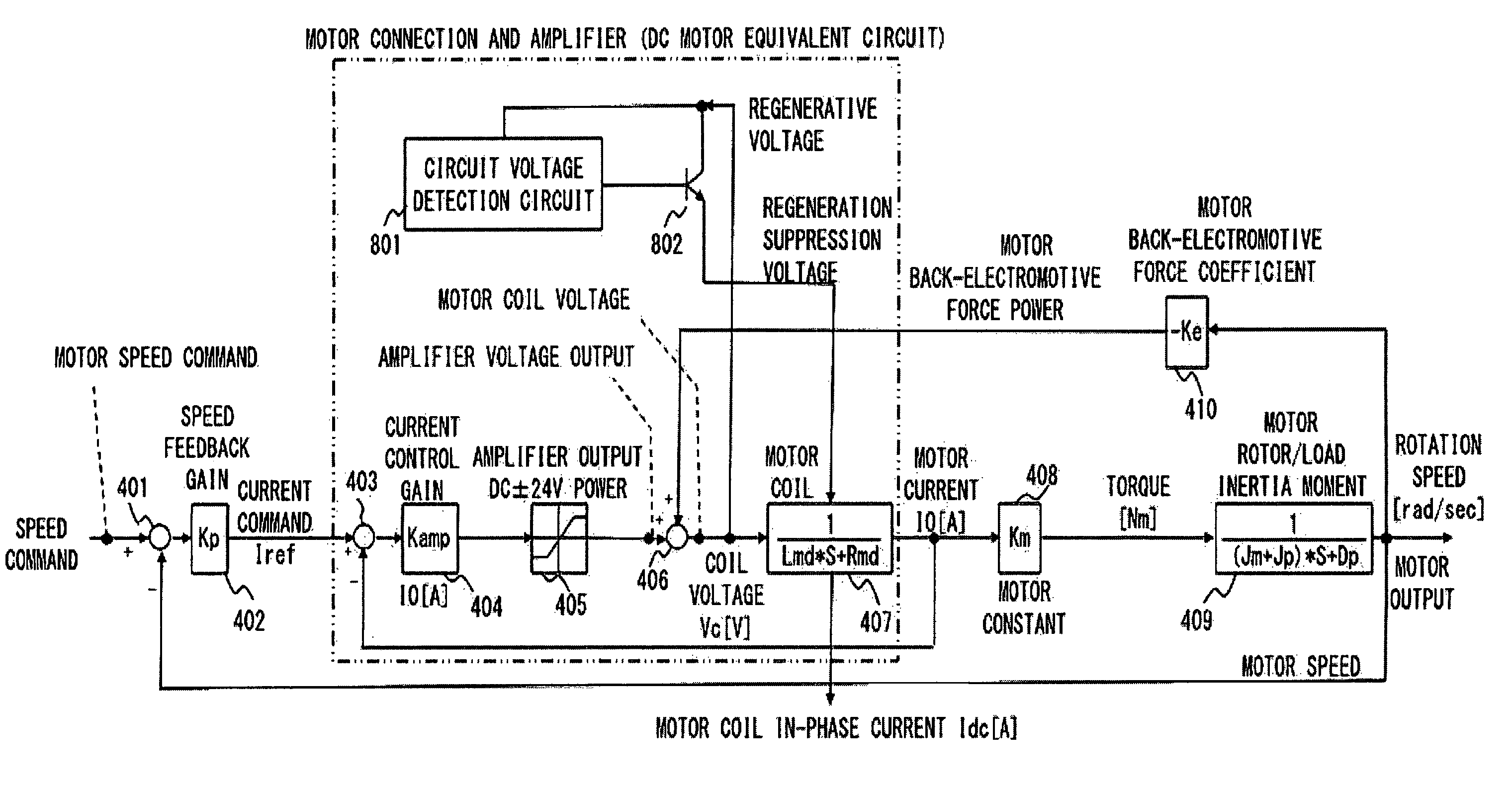
Accordingly, if a motor is used in a system such as a vehicle, the motor acts as an electric generator when a vehicle moves down a downward slope, so that a voltage undesirably increases to exceed a withstand voltage.
However, the regenerative resistor or capacitor 413 has a large weight and volume.
This causes an increase in the mass or size of a vehicle, robot or the like in which the above motor is used.
This hinders the achievement of size or weight reduction of a vehicle, robot or the like in which the motor is used.

Method used


Image

  • Motor control apparatus and motor control method
  • Motor control apparatus and motor control method
  • Motor control apparatus and motor control method

Examples


Embodiment Construction

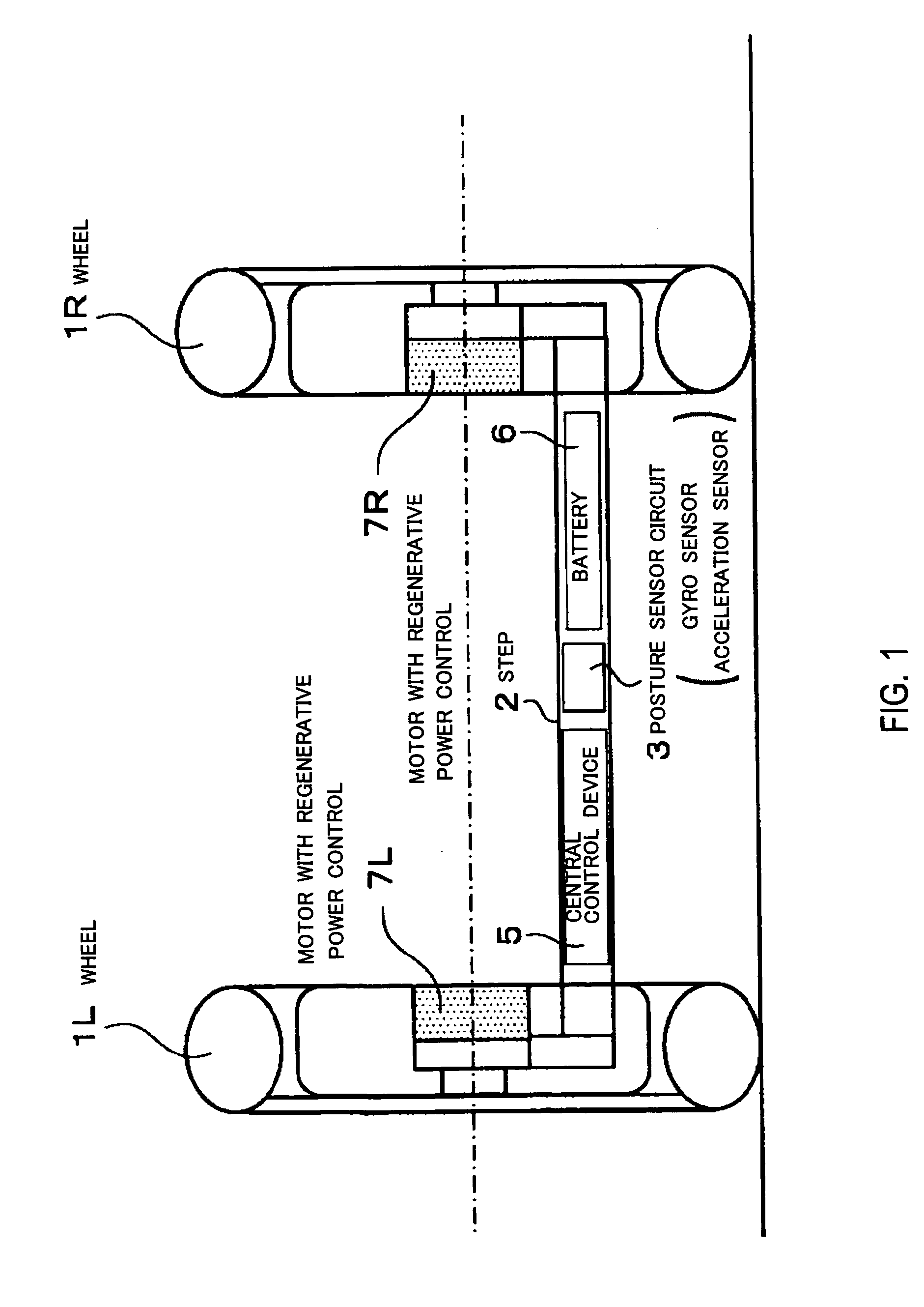
[0060]An embodiment of the present invention is described hereinafter with reference to the drawings. FIG. 1 schematically shows a wheel configuration to which the motor control apparatus and the motor control method according to an embodiment of the present invention is applied. In the following description, the same elements as in the configuration described in the above related art are denoted by the same reference symbols.

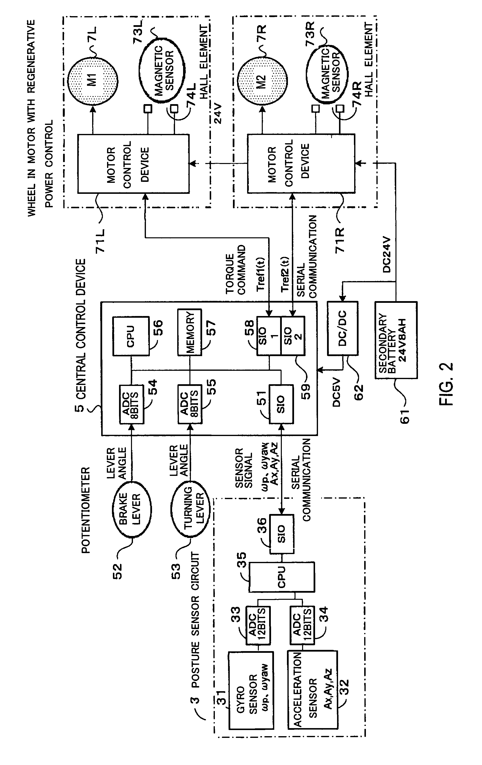
[0061]Referring to FIG. 1, a step 2 on which a passenger stands is placed lower than the axle of left and right wheels 1L and 1R. The step 2 includes a posture sensor circuit 3 which has a gyro sensor and an acceleration sensor, and a central control device 5 which controls motors 7L and 7R that drives the wheels 1L and 1R according to the output of the posture sensor circuit 3. The step 2 further includes a battery 6, from which a power is supplied to the posture sensor circuit 3, the motors 7L and 7R and the central control device 5.

[0062]The configuration of...


PUM


Abstract

Size and weight reduction of a motor-driven vehicle, robot or the like is achieved. A current command Iref from a speed feedback gain is supplied to each of circuits with coefficients of sin(θm), sin(θm+2π / 3) and sin(θm−2π / 3) to generate three-phase signals. The three-phase signals are respectively supplied to current control gains through adder-subtracters. Further, signals from motor constants are added together by an adder to produce motor torque. Furthermore, coil voltages output from adders pass through diodes and are then added together by an adder, and the signal is supplied to a regenerative voltage determiner. When a regenerative voltage becomes excessive, in-phase current Idc is supplied through a regeneration control gain to adder-subtracters.

Description

BACKGROUND OF THE INVENTION[0001]1. Field of the Invention[0002]The present invention relates to a motor control apparatus and a motor control method which are suitable for use in controlling a motor in an electric vehicle, an articulated robot system or the like. Particularly, the present invention enables an electric motor to generate a regenerative power with the suitable consumption.[0003]2. Description of Related Art[0004]The inventors of the present invention have proposed a two-wheel vehicle for assisting people movement (cf. e.g. Japanese Unexamined Patent Application Publication No. 2005-138631).[0005]Further, a technique of consuming a regenerative power which is generated by a motor has been proposed (cf. e.g. Japanese Unexamined Patent Application Publication No. 2000-116190).[0006]FIG. 13 shows the configuration of a vehicle having a wheel configuration (two wheels or three or more wheels) to which the present invention is applicable and employing inverted pendulum cont...

Claims


Application Information

Patent Timeline
Patent Type & Authority Patents(United States)
IPC IPC(8): G05B11/18
CPCH02P21/0003H02P21/0035H02P21/22
Inventor ISHII, SHINJI
Owner TOYOTA JIDOSHA KK
Learn More