Biopsy localization method and device

a biopsy and localization technology, applied in the field of biopsy localization methods and devices, can solve the problems that surgeons often have difficulty in determining the precise relationship of previously excised tissue to the surgical wound

Inactive Publication Date: 2006-04-13
FULTON RICHARD E +1
View PDF100 Cites 114 Cited by
  • Summary
  • Abstract
  • Description
  • Claims
  • Application Information

AI Technical Summary

Benefits of technology

[0006] The present invention is directed to a biopsy localization method and device which uses a locatable bioabsorbable element left at the biopsy site so that if testing of the biopsy sample indicates a need to do so, the biopsy site can be relocated by finding the bioabsorbable element. This eliminates the need to use of metallic clips during biopsies and often eliminates the need for a return to the radiologist for preoperative needle localization. In addition, the bioabsorbable element can be used as a therapeutic tool for treatment of the diseased lesion and for hemostasis.
[0008] One preferred material used as the bioabsorbable element is a dehydrated collagen plug. This type of plug may swell and is palpable for subsequent location by the surgeon. The collagen plug may not swell at all. In some situations, such as with small breasted women or where the biopsy site is close to the surface, a non-swellable bioabsorbable material, such as a round pellet of PGA, can be used instead of a swellable bioabsorbable material. The bioabsorbable material can also be made so that it is absorbed quickly to produce a local tissue inflammation; such a localized inflammation can be used to locate the biopsy site instead of location by palpation. Instead of leaving, for example, a collagen plug, a PGA pellet or a bioabsorbable suture material at the biopsy site for location by palpation or inflammation, a length of bioabsorbable suture material, a collagen filament, or other bioabsorbable material extending from the biopsy site out through the skin can be used. In this case the surgeon can follow the bioabsorbable suture material to the biopsy site in a manner similar to that used with Hawkins needles. In other cases, such as in the case of a deeply located lesion or large breast, the bioabsorbable material may need to be located by the radiologist, by for example, ultrasound or mammography. In any event the bioabsorbable material will typically be absorbed within about a month of placement. The invention thus eliminates the use of metal clips during biopsies and usually eliminates the need for return to the radiologist for preoperative localization.
[0012] The change in the bioabsorbable element can be via one of several ways, such as hydration or desiccation, change in temperature, electrical stimulation, magnetic stimulation, chemical or physical reaction with another material, additives, enzymatic reactions, ionization, electrical charges, absorption, as well as other means. The invention may employ one or more of these techniques or measures or others, to change the consistency, hardness and or size of the bioabsorbable element between its deployed and non-deployed states. The visual detectability of the bioabsorbable element may be aided by the use of a coloring agent, such as methylene blue or some other dye. The radiographic detectability of the element may be enhanced by a radiopaque marker. As well, ultrasonic detectability may be enhance by special treatment of the bioresorbable element.
[0014] The provision of hemostasis helps to lessen the bleeding and swelling within and about the biopsy site. This can be accomplished by physical or chemical means. That is, the device may swell so that it essential fills the biopsy cavity or the device may have a chemical reaction with blood or blood products to cause effective blood clotting, or both. Other methods for causing local hemostasis are also possible with the invention.

Problems solved by technology

For example, during a wide surgical excision for cancer diagnosed by a recent surgical excisional biopsy, surgeons frequently have difficulty in determining the precise relationship of the previously excised tissue to the surgical wound.

Method used


Image

  • Biopsy localization method and device
  • Biopsy localization method and device
  • Biopsy localization method and device

Examples


Embodiment Construction

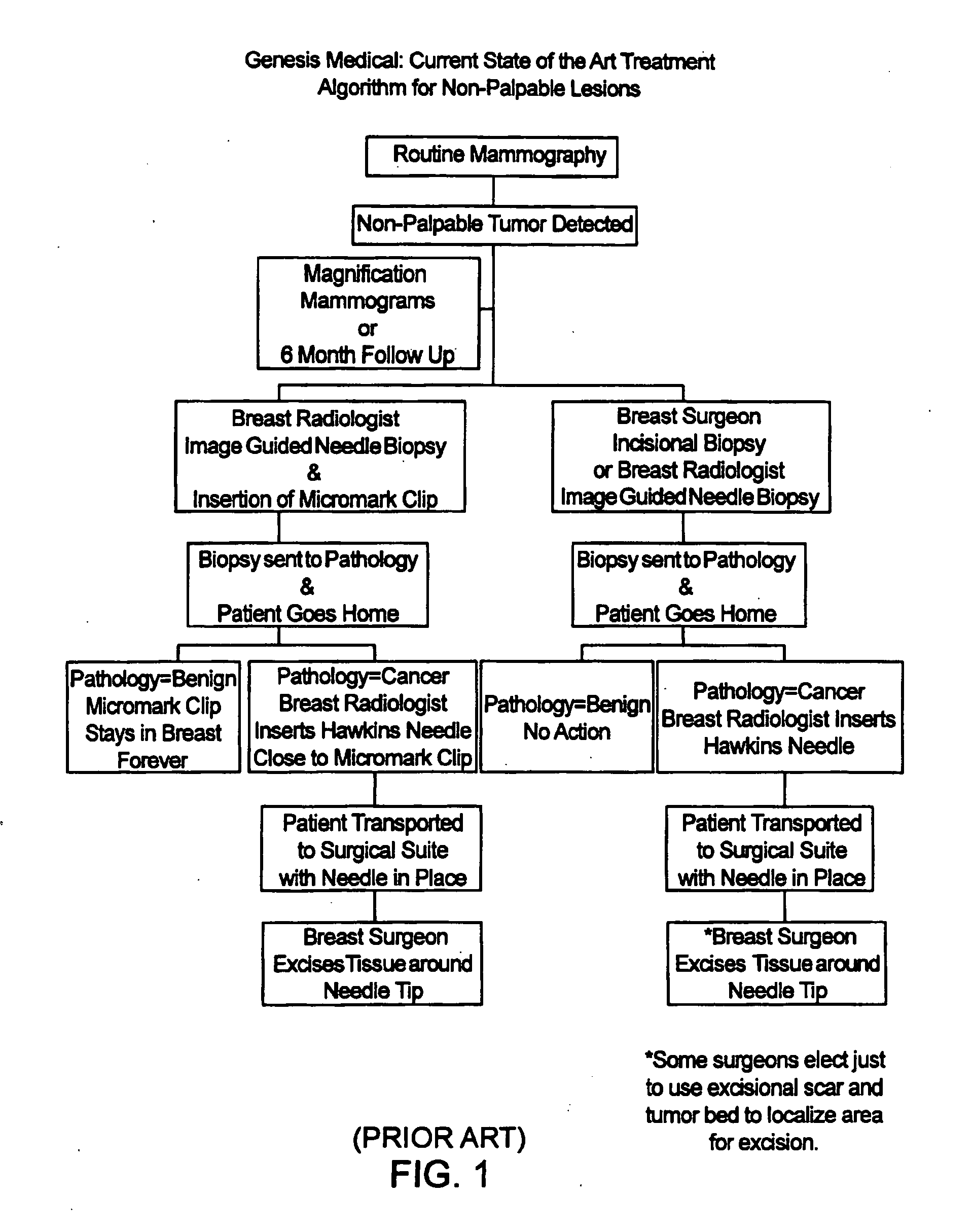
[0023]FIG. 2 illustrates a treatment algorithm 2 according to the present invention. As a result of a routine mammography 4, a tumor or other abnormality may be detected as at 6. The typical response will often include additional magnification mammograms or a follow-up mammogram scheduled for some time in the future, such as six months. This is indicated at 8. If the tumor is not palpable, see 9, an image guided needle biopsy by a breast radiologist is typically conducted as at 10. Image guided needle biopsies can be done in a number of ways. Presently, stereotactic (x-ray) and ultrasound guided needle biopsies are commonly used, primarily because of their accuracy, speed and minimal trauma to the patient. Stereotactic needle biopsies typically use a stereotactic table, such as made by Fisher or Lorad, which provides mammography (x-ray) guidance to a biopsy needle assembly. Ultrasound guided biopsies can be conducted with any one of a number of commercially available instruments. An...


PUM


Abstract

A biopsy localization device made according to the invention includes an intracorporeal delivery cannula and at least one marker disposed within an inner lumen of the delivery cannula. The marker includes an expandable fibrous body with at least one radiographically detectable marker element. The expandable fibrous body may also be bioabsorbable. Methods of use of the device are also described.

Description

[0001] This application is a continuation of U.S. application Ser. No. 10 / 839,226, filed May 4, 2004, which is a continuation of U.S. application Ser. No. 10 / 027,157, filed Dec. 20, 2001, now issued as U.S. Pat. No. 6,730,042, which is a continuation of U.S. application Ser. No. 09 / 900,801, filed Jul. 6, 2001, now issued as U.S. Pat. No. 6,699,205, which is a continuation of U.S. application Ser. No. 09 / 366,360, filed Jun. 18, 1999, now issued as U.S. Pat. No. 6,270,464, which application claims the benefit of the following provisional patent applications: Biopsy Localization Device, Application No. 60 / 090,243, filed Jun. 22, 1998; Biopsy Localization and Hemostasis Device, Application No. 60 / 092,734, filed Jul. 14, 1998; Device and Method of Biopsy Localization and Hemostasis, Application No. 60 / 114,863, filed Jan. 6, 1999; and Device and Method of Biopsy Localization, Hemostasis & Cancer Therapy, Application No. 60 / 117,421, filed Jan. 27, 1999.BACKGROUND OF THE INVENTION [0002] In...

Claims


Application Information

Patent Timeline
Patent Type & Authority Applications(United States)
IPC IPC(8): A61F13/20A61B17/34A61B10/00A61B6/00A61B10/02A61B19/00
CPCA61B6/502A61B10/02A61B17/3421A61B17/3468A61B19/54A61B2017/00004A61B2019/5408A61B2019/5462A61B2019/5487A61B2090/3962A61B2090/3908A61B2090/3987A61B90/39
Inventor FULTON, RICHARD E.DUBRUL, WILLIAM RICHARD
Owner FULTON RICHARD E
Why Eureka
Try Eureka