
Magnetic tape, its cleaning method, and optical servotrack forming/cleaning apparatus

Inactive Publication Date: 2010-09-28
FUJIFILM CORP
View PDF29 Cites 114 Cited by
  • Summary
  • Abstract
  • Description
  • Claims
  • Application Information

AI Technical Summary

Benefits of technology

[0022]If the ratio of carbon black in the nonmagnetic powder is increased to 80 wt. % or more, it becomes easy to form the pits for optical servo (i.e., servo holes) by irradiation with laser beams. The addition of 20 wt. % or less of iron oxide (e.g., red iron oxide) in combination with carbon black is effective to improve the strength of the backcoat layer.
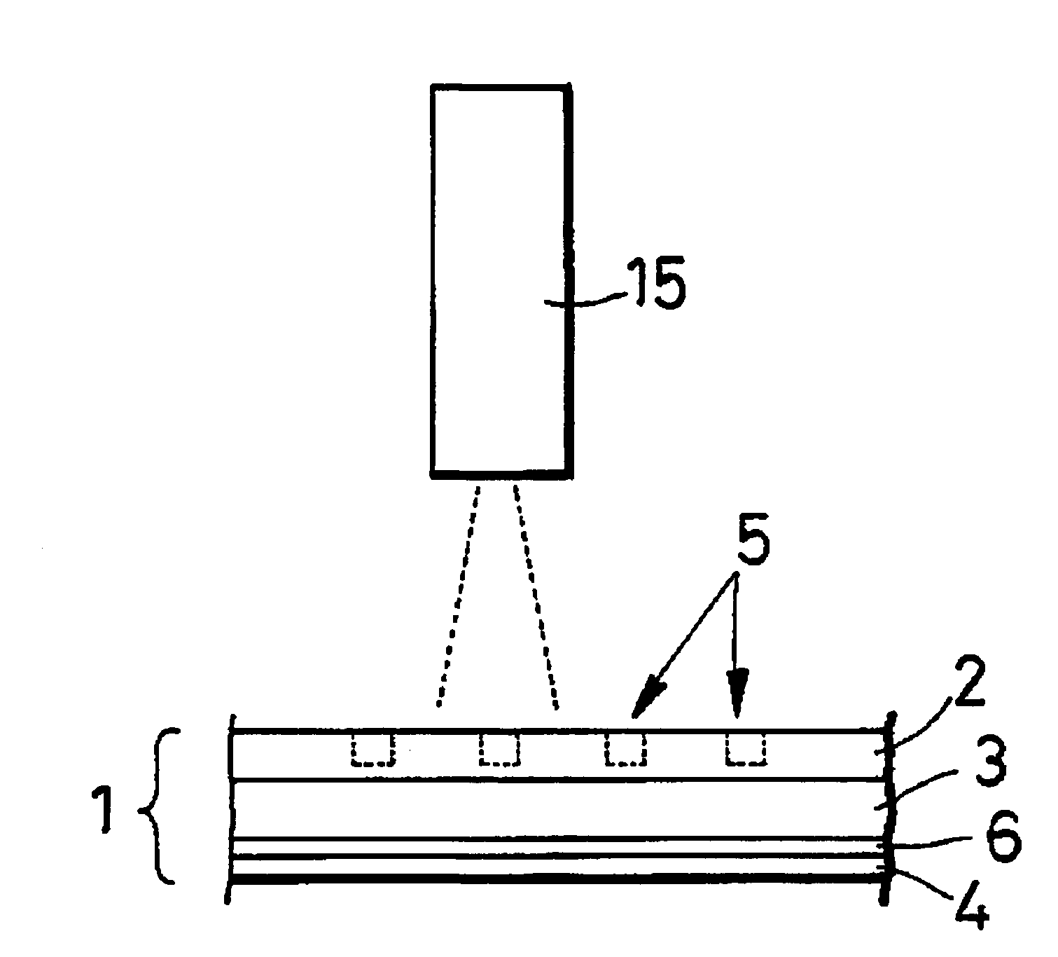
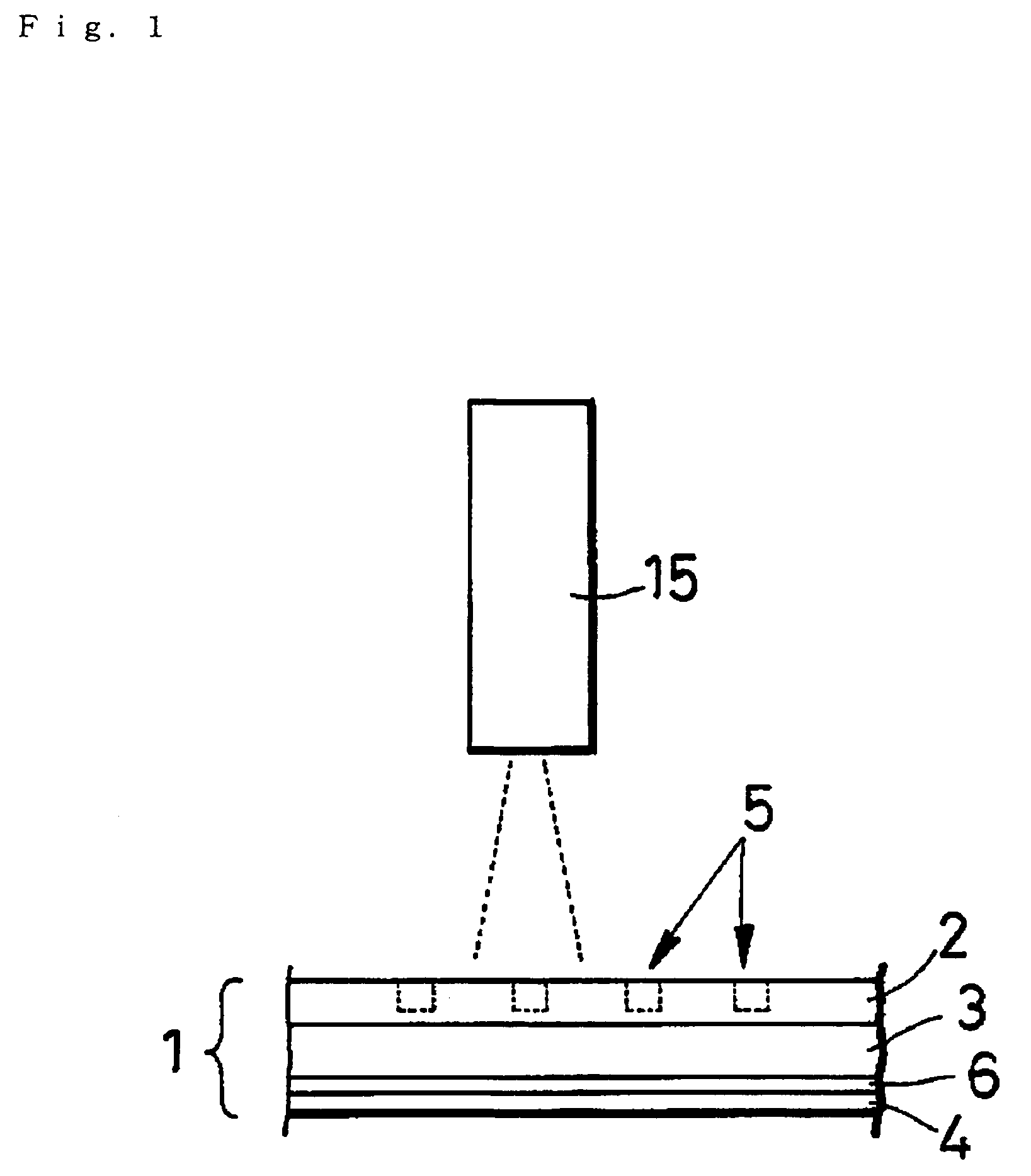
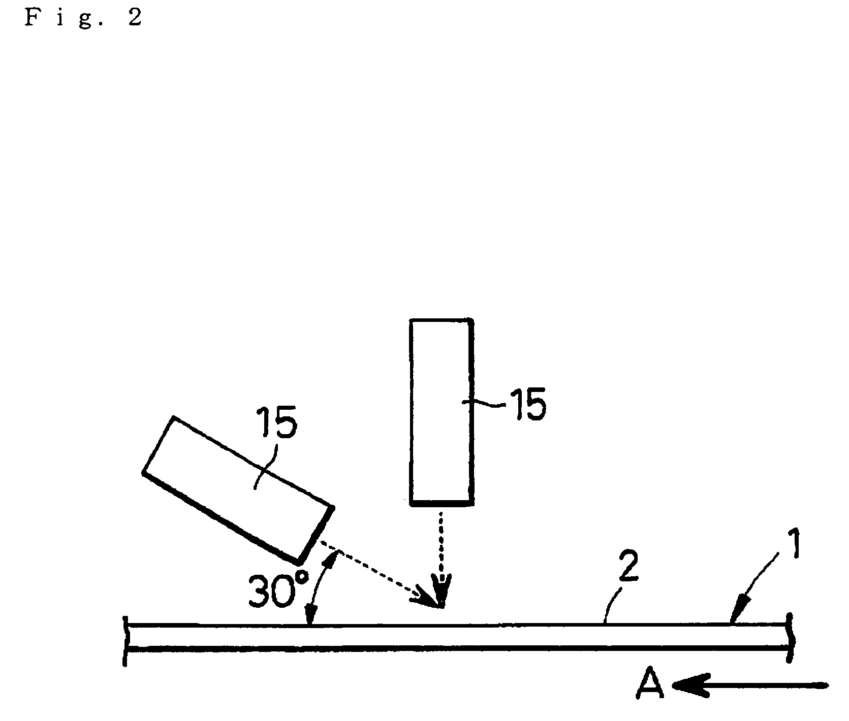
[0024]Another object of the present invention is to provide a method and an apparatus for efficiently removing the burnt residue (powder, etc.) which form when pits for optical servo are formed on the backcoat layer of a magnetic tape by irradiation with laser beams and which adhere to the interiors of the pits and their peripheries on the backcoat layer, and also to provide a magnetic tape having a low error rate.
[0025]As a result of the researches of a method for efficiently removing such burnt residues, the following methods are found to be effective: (1) cleaning by using CO2, and (2) cleaning by using a raised fabric or the like. The method (1) using CO2 requires a relatively large-scale apparatus, while it is relatively low in running cost, since only consumable is CO2. On the other hand, the method (2) using a raised fabric requires a relatively simple apparatus, although consuming raised fabrics.

Problems solved by technology

When the recording wavelength is shortened, the influence of spacing between the magnetic layer and the magnetic heads becomes serious.
Thus, if the magnetic layer has large projections or dents, an output decreases due to spacing loss, and thus an error rate increases.
In particular, when the backcoat layer having such pits is irradiated with light, light randomly reflects on the pits, and therefore, the intensity of reflected light which enters an optical detector is low.
However, the intensity of light which reflects on the flat portion of the backcoat layer of a conventional magnetic tape is low, and the reflectance on the flat portion largely fluctuates depending on a site of the magnetic tape.
Thus, it is impossible to sufficiently increase the ratio of S / N of optical servo signals.
In case where pits are formed in a backcoat layer by irradiation with laser beams or by depression with a stamper, the peripheries (or the edges) of the pits are inevitably raised, which causes the following problems.
In this case, if the specific positions of the magnetic tape are raised as described above, the track-formed portion of the tape wound onto a reel becomes extremely high, which results in a disorder in the winding of the tape.
In addition, if the tape has the raised portions as described above, they are pressed against the side of the recording layer (magnetically recording surface) of the magnetic tape, so that the surface of the recording layer becomes uneven, which results in low reproduction output.
That is, these problems are peculiar to the magnetic tapes.
This method provides higher productivity, however, has a problem in that the numerous particles of burnt residues as the result of the laser baking for forming a pattern, undesirably, adhere to the pits and their peripheries.
If the burnt residues are left as they are, they cause not only contamination of the tape-running system but also decrease in the ratio of S / N of optically read signals on the backcoat layer and the dropping-out of the magnetic layer due to the adhesion of the burnt residues.
If this method is applied to clean a magnetic tape, the total surface area of the lengthy tape to be cleaned is enormous, and the amount of solid CO2 blown onto the tape a lot of times becomes far larger as compared with the disc.
Therefore, the cleaning efficiency is poor.
The magnetic tape confronts a further problem from which the floptical disc has never suffered: that is, the burnt residues remaining after the formation of the servo pattern by irradiation with laser beams adhere and transfer when the magnetic tape is again wound, and such burnt residues, in turn, adhere to the drive guide roller and the magnetic heads.
This method is unsatisfactory, because the cleaning of the flat portion of the backcoat layer is insufficient, and also the effect of cleaning the interiors of servo dots formed as pits by laser beams is poor.
However, a strong blade treatment may damage the backcoat layer, since the backcoat layer has a lower strength than the magnetic layer.
On the contrary, if a weak blading treatment is made on the backcoat layer, the burnt residues thereon cannot be removed.
Thus, this method is unsuitable for large-scale production, because selection of the conditions for the cleaning is difficult.
Still worse, this method has substantially no effect of cleaning the interiors of the servo dots formed as the pits.

Method used


Image

  • Magnetic tape, its cleaning method, and optical servotrack forming/cleaning apparatus
  • Magnetic tape, its cleaning method, and optical servotrack forming/cleaning apparatus
  • Magnetic tape, its cleaning method, and optical servotrack forming/cleaning apparatus

Examples


example 1

[0127]

(1)Iron oxide powder (particle size: 0.11 × 0.02 μm)68partsα-Alumina (particle size: 0.07 μm)8partsCarbon black (particle size: 25 nm;24partsoil absorption: 55 g / cc)Stearic acid2.0partsVinyl chloride-hydroxypropyl acrylate copolymer8.8parts(—SO3Na group content: 0.7 × 10⁻⁴ eq. / g)Polyesterpoyurethane resin4.4parts(Tg: 40° C., —SO3Na group content: 1 × 10⁻⁴ eq. / g)Cyclohexanone25partsMethyl ethyl ketone40partsToluene10parts(2)Butyl stearate1partCyclohexanone70partsMethyl ethyl ketone50partsToluene20parts(3)Polyisocyanate(Colonate L manufactured by Nippon Polyurethane)4.4partsCyclohexanone10partsMethyl ethyl ketone15partsToluene10parts

[0128]

(A)Ferromagnetic iron metal powder100parts(Co / Fe: 30 atomic %, Y / (Fe + Co): 3 atomic %,Al / (Fe + Co): 5 wt. %, Ca / Fe: 0;σs: 155 A · m2 / kg, Hc: 188.2 kA / m, pH: 9.4,major axis length: 0.10 μm)Vinyl chloride-hydroxypropyl acrylate copolymer12.3parts(—SO3Na group content: 0.7 × 10⁻⁴ eq. / g)Polyesterpolyurethane resin5.5parts(—SO3Na group content: 1 ×...

example 2

[0151]A magnetic tape was obtained substantially in the same manner as in Example 1, except that the calendering conditions were changed, that is, the temperature and the linear pressure were changed from 100° C. and 147 kN / m (150 kgf / cm) to 90° C. and 294 kN / m (300 kgf / cm).

example 3

[0152]A magnetic tape was obtained substantially in the same manner as in Example 1, except that the calendering conditions were changed, that is, the temperature and the linear pressure were changed from 100° C. and 147 kN / m (150 kgf / cm) to 120° C. and 294 kN / m (300 kgf / cm).


PUM


Abstract

A magnetic tape which comprises a nonmagnetic support, a magnetic layer which is formed on one surface of the nonmagnetic support, and a backcoat layer which comprises a binder and nonmagnetic powder containing carbon black as a component and which is formed on the other surface of the nonmagnetic support, having pits for optical servo formed thereon, characterized in that the average of the reflectance on the flat portion of the backcoat layer is 8.5% or higher, and that the maximum rate of fluctuation of the reflectance on the flat portion, depending on a position of the magnetic tape:[Maximum of absolute value of (Reflectance−Average reflectance)]×100 / (Average reflectance)is 10% or lower. This magnetic tape is high in the initial S / N of the servo signal, and also high in the S / N of the servo signal found after the magnetic tape is run twice.

Description

[0001]This application is the national phase under 35 U.S.C. §371 of PCT International Application No. PCT / JP01 / 11610 which has an International filing date of Dec. 28, 2001, which designated the United States of America.TECHNICAL FIELD[0002]The present invention relates to a magnetic tape in which pits for optical servo tracks are formed on a backcoat layer, a method for cleaning a magnetic tape, and an apparatus for forming and cleaning optical servo tracks.BACKGROUND ART[0003]Magnetic tapes have found various applications in audio tapes, videotapes, data backup tapes for computers, etc. In particular, in the field of magnetic tapes for data-backup (or backup tapes), tapes having memory capacities of several tens GB or more per one reel are commercialized in association with increased capacities of hard discs for back-up. Therefore, it is inevitable to increase the capacity of this type of a tape for data-backup so as to correspond to a further increased capacity of a hard disc. I...

Claims


Application Information

Patent Timeline
IPC IPC(8): G11B5/706G11B5/584G11B5/735G11B5/78G11B23/50
CPCG11B23/502G11B5/78G11B5/735G11B5/584G11B5/7358
Inventor OTA, HIROYUKIFUJISAWA, HARUHIKOMUKAI, NAOKIFUKIAGE, SATORUSANO, KENJIFUJITANI, SHIGEO
Owner FUJIFILM CORP
Learn More