
Coupled-inductor multi-phase buck converters

a multi-phase buck converter and coupled-inductor technology, which is applied in the direction of electric variable regulation, process and machine control, instruments, etc., can solve the problems of increasing either or both switching frequency or control bandwidth, requiring a wide control bandwidth, and avoiding the necessity of increasing winding length. , to achieve the effect of improving physical symmetry

Inactive Publication Date: 2010-09-07
VIRGINIA TECH INTPROP INC
View PDF7 Cites 21 Cited by
  • Summary
  • Abstract
  • Description
  • Claims
  • Application Information

AI Technical Summary

Benefits of technology

This design enhances control bandwidth and transient response without increasing switching frequency, reduces copper losses, and improves efficiency by balancing ripple currents and accommodating preferred motherboard layouts, while maintaining high power density and cost-effectiveness.

Problems solved by technology

A high rate of change of current requirements of a load requires a wide control bandwidth which, as a practical matter is generally limited to about one-sixth of the switching frequency.
While increasing control bandwidth can, in theory, be accomplished by increasing switching frequency, as a practical matter, increasing either or both of the switching frequency or the control bandwidth is a difficult technical challenge for several reasons such as developing sufficiently high voltage regulation resolution within a short switching cycle and accommodation of voltage sampling constraints for control through feedback (which imposes the limit of about one-sixth of the switching frequency on the control bandwidth due to sample-and-hold circuit effects, particularly if adaptive voltage positioning (AVP) is required, as well as increased losses due to, for example, body diode conductance of switches.
Meeting transient load requirements for current and foreseeable microprocessor design require filter storage capacitance of 30 capacitors of 100 μF each or eight capacitors of 560 μF each which is prohibitive and unacceptable in terms of both cost and footprint.
However, the known commercial coupling structure has the disadvantage that, in order to make the inverse coupling between phases, the windings must be around the core legs.
Further, the winding length must be greater than in the non-coupled inductor and one more copper trace is needed in the layout to connect to the switching node as shown in FIG. 1B, increasing copper losses due to the longer trace.
Additionally, the core of the known commercial coupling inductor is not flexible or physically symmetrical to match the preferred power stage layout and the voltage regulator arrangement in preferred layouts for a motherboard of current processor designs.
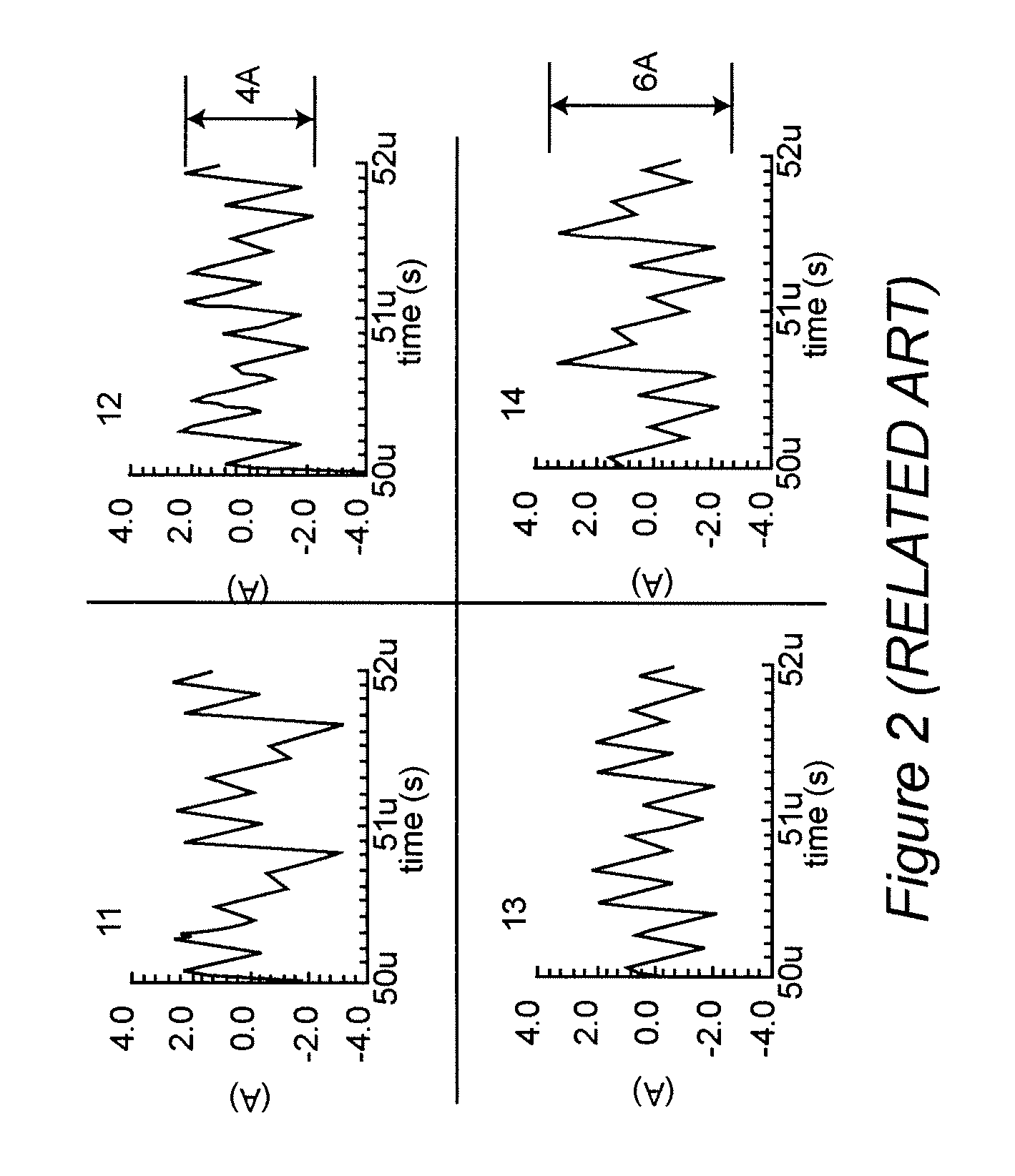
These unavoidable physical constraints cause severely unbalanced ripple currents of each phase, as shown in FIG. 2 for a four phase embodiment.
However, this approach is very complex and requires a large number of magnetic components to be provided at a high cost and thus is unacceptable.

Method used


Image

  • Coupled-inductor multi-phase buck converters
  • Coupled-inductor multi-phase buck converters
  • Coupled-inductor multi-phase buck converters

Examples


Embodiment Construction

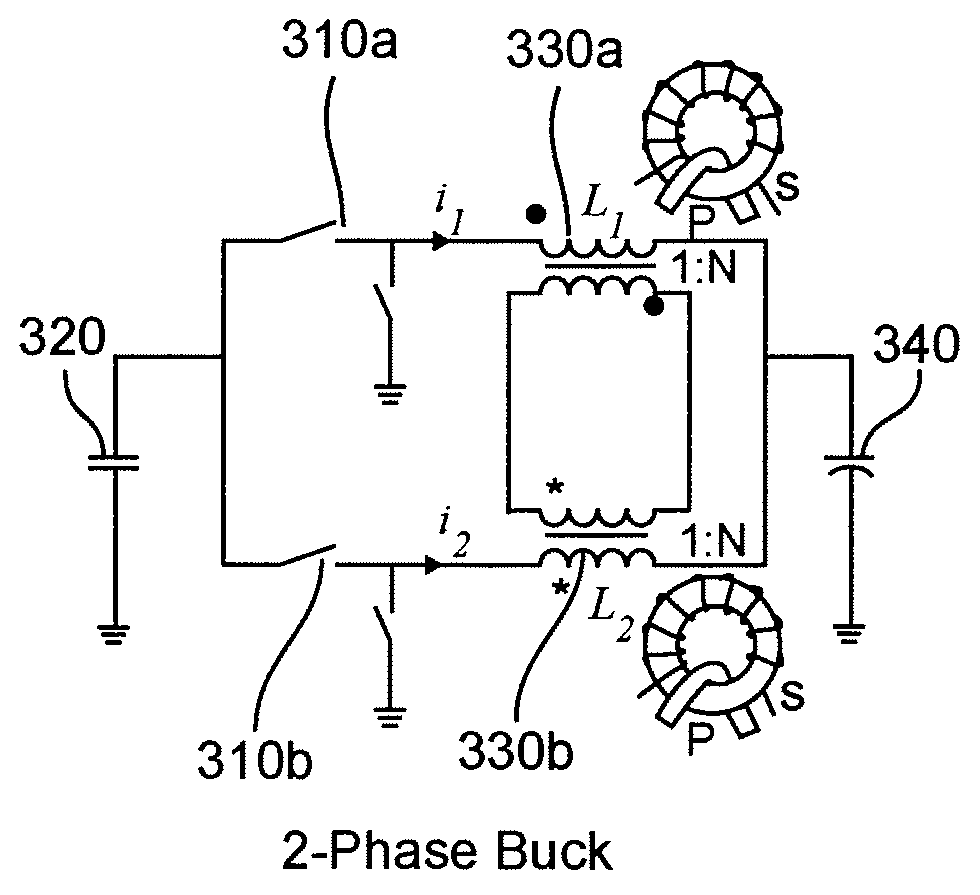
[0021]Referring now to the drawings, and more particularly to FIG. 3A, there is shown a schematic diagram of a two-phase buck converter including a coupled inductor in accordance with the invention. Those skilled in the art will immediately recognize that the circuit of FIG. 3A is essentially two single-phase buck converters connected in parallel but with secondary windings on the respective inductors therein (e.g. forming transformers, preferably on cores, as depicted, with the primary and secondary windings indicated by “P” and “s”, respectively) which are connected in an opposing relationship as indicated by the symbols “●” and “*”. The basic operation of the buck converters without such connected secondary windings is that the switching arrangements 310a and 310b, each including so-called top and bottom switches, connect a power source 320 to the inductors 330a and 330b for short intervals of time through respective top switches in an alternating manner between the respective bu...


PUM


Abstract

In a multi-phase power converter, efficiency is increased and ripple reduced while maintaining transient response and dynamic performance improved by electrically coupling secondary windings of transformers or provided for inductors of respective phases such that current to a load is induced in each phase by current in another phase. Magnetic coupling can also be provided between phases using a multi-aperture core of a configuration which minimizes primary winding length and copper losses. Efficiency at light load is enhanced by controlling current in the series connection of secondary windings in either binary or analog fashion.

Description

BACKGROUND OF THE INVENTION[0001]1. Field of the Invention[0002]The present invention generally relates to voltage regulators (VRs) and voltage regulator modules (VRMs) and, more particularly, to switching VRs and VRMs having broad bandwidth to accommodate requirements for rapid transient response and with low steady-state current ripple such as are increasingly demanded for powering current and foreseeable microprocessors and the like.[0003]2. Description of the Prior Art[0004]Most electronic devices are ultimately powered with a direct current (DC) voltage even though power is often initially obtained from an alternating current (AC) power distribution system. Many such devices also require close voltage regulation of the power supply to function properly and reliably even when power is provided from a DC voltage source such as batteries. Microprocessors and other digital processing circuits using integrated circuits with high speed clocks and / or of high integration density requir...

Claims


Application Information

Patent Timeline
Patent Type & Authority Patents(United States)
IPC IPC(8): G05F1/59
CPCH02M3/1584H01F17/045H01F30/06H01F2038/006
Inventor XU, MINGLEE, FRED C.YING, YUCHENG
Owner VIRGINIA TECH INTPROP INC
Learn More