Plasma doping method
a technology of plasma and ionization, applied in the direction of basic electric elements, semiconductor/solid-state device manufacturing, electric devices, etc., can solve the problems of reducing the number of implantation throughput, and reducing the number of ions to be extracted, so as to achieve high precision, increase the process window, and the effect of high precision
- Summary
- Abstract
- Description
- Claims
- Application Information
AI Technical Summary
Benefits of technology
Problems solved by technology
Method used
Image
Examples
first embodiment
[0095]A plasma doping method according to a first embodiment of the present invention will now be described with reference to the drawings.
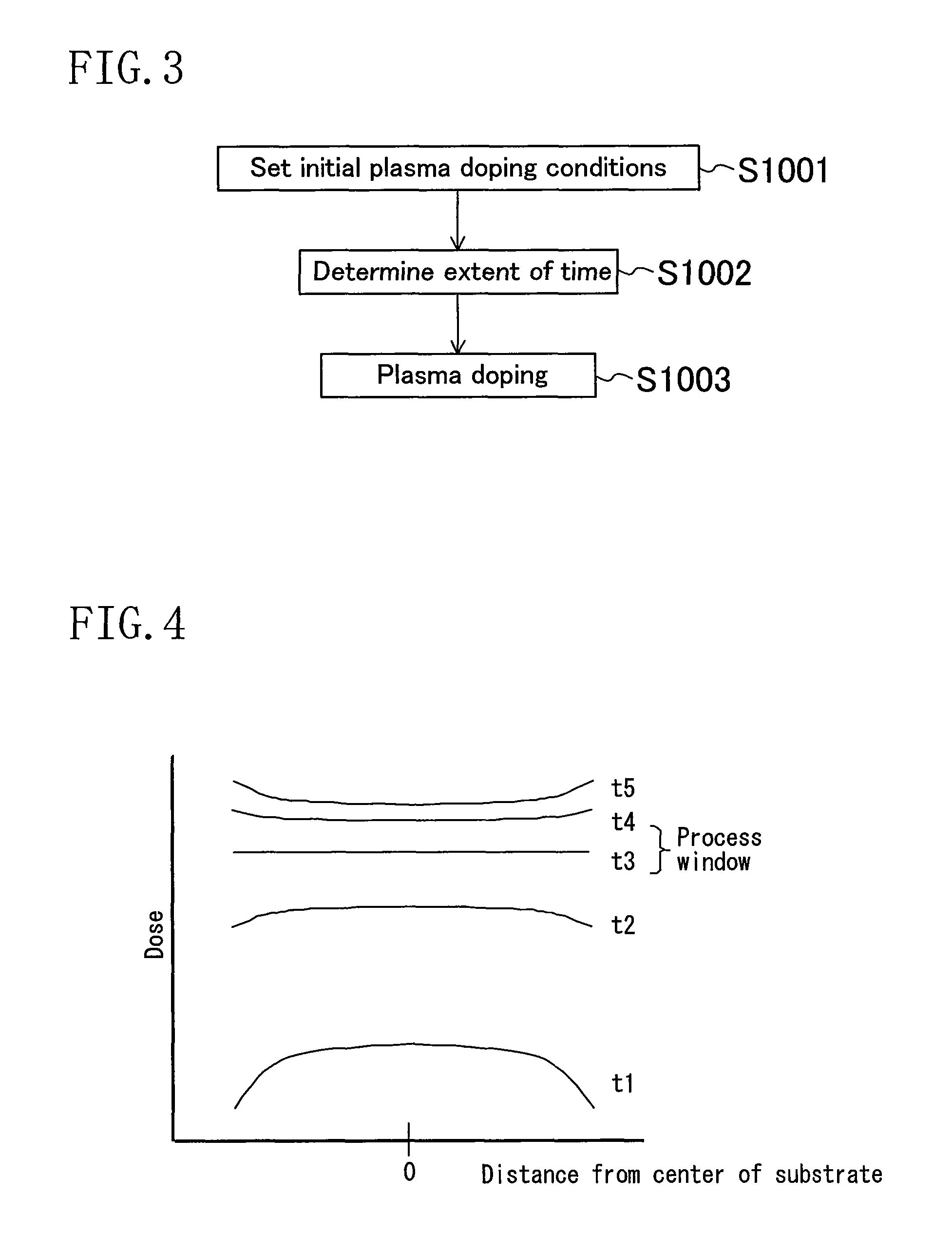
[0096]The plasma doping method of the present embodiment is characterized in that the method makes use of the phenomenon that the magnitude relationship between the dose in the substrate central portion and that in the substrate peripheral portion is reversed as the doping process time increases, and that the method uses the time at which the magnitude relationship is reversed, i.e., the time at which the dose in the substrate central portion and that in the substrate peripheral portion are equal to each other, as the process window of plasma doping time.
[0097]Thus, in the plasma doping method of the present embodiment, the substrate is plasma-doped with an impurity under a plasma doping condition set with respect to the dose of the impurity to be introduced into the substrate so that a first one of doses in the central portion and in the periphe...
second embodiment
[0125]A plasma doping method according to a second embodiment of the present invention will now be described with reference to the drawings.
[0126]In the first embodiment described above, the plasma doping condition is set so that the impurity dose distribution across the principal plane of the substrate is in rotational symmetry during the initial period of doping. In contrast, in the present embodiment, plasma doping condition is set so that the impurity dose distribution across the principal plane of the substrate has a gradient along at least one diameter passing through the center of the substrate during the initial period of doping, after which the plasma doping condition is changed so that the gradient in the distribution is reversed.
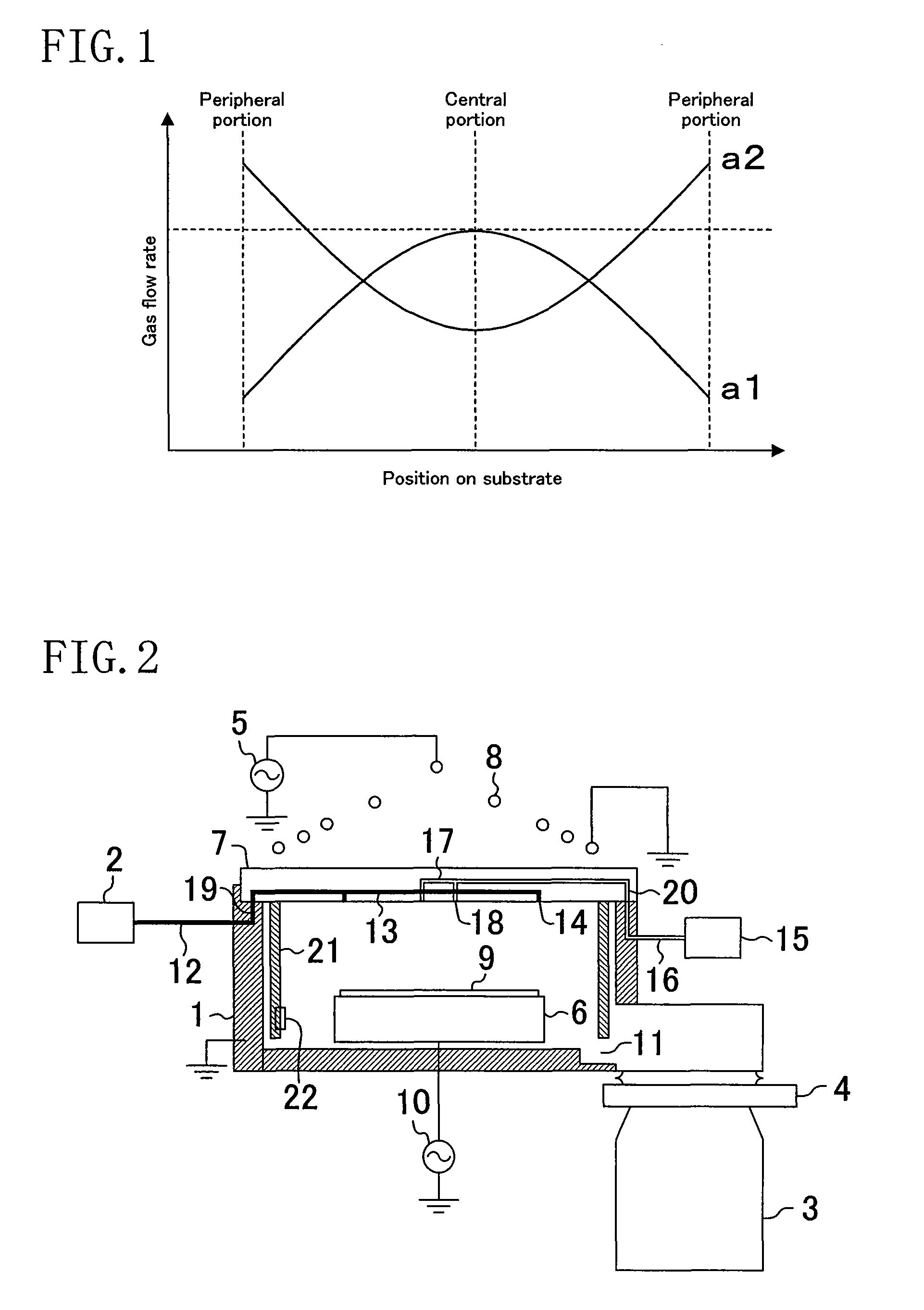
[0127]FIG. 6 shows an example of how the plasma doping condition is set in the plasma doping method of the present embodiment. Specifically, the plasma doping condition is set so that the distribution of the flow rate of the gas (plasma-generating...
third embodiment
[0131]A plasma doping method according to a third embodiment of the present invention will now be described with reference to the drawings.
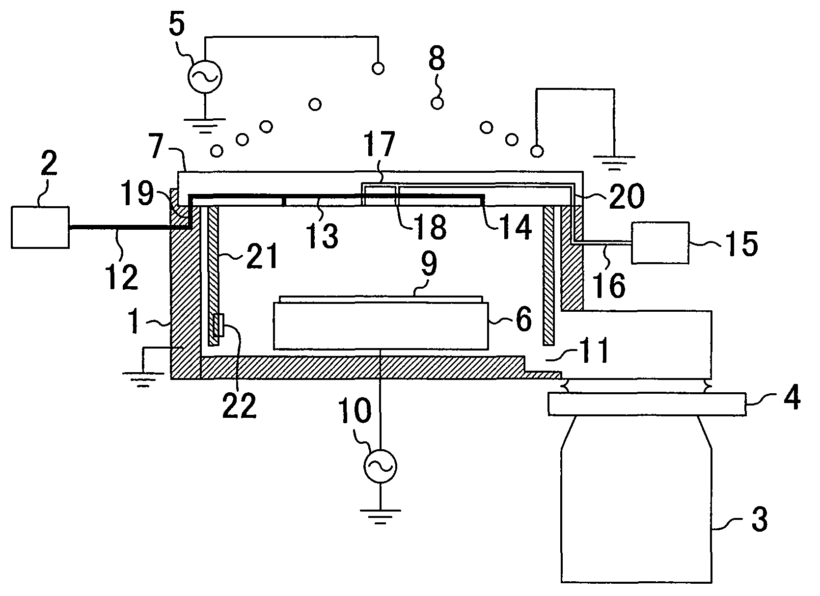
[0132]FIG. 9 is a cross-sectional view showing an example of a configuration of a plasma doping apparatus for use in carrying out the plasma doping method of the present embodiment, and FIG. 10 is an enlarged cross-sectional view showing a gas supply port being an important part of the plasma doping apparatus shown in FIG. 9. In the plasma doping apparatus shown in FIG. 9, like elements to those of the plasma doping apparatus shown in FIG. 2 and described above in the first embodiment are denoted by like reference numerals, and will not be described below.
[0133]The basic configuration of the plasma doping apparatus shown in FIGS. 9 and 10 is similar to that of the plasma doping apparatus shown in FIG. 2, but has differences as follows. Specifically, the plasma doping apparatus shown in FIGS. 9 and 10 is provided with only the first gas supplying ...
PUM
 Abstract
Description
Claims
Application Information
 - R&D
- Intellectual Property
- Life Sciences
- Materials
- Tech Scout
- Unparalleled Data Quality
- Higher Quality Content
- 60% Fewer Hallucinations
Browse by: Latest US Patents, China's latest patents, Technical Efficacy Thesaurus, Application Domain, Technology Topic, Popular Technical Reports.
© 2025 PatSnap. All rights reserved.Legal|Privacy policy|Modern Slavery Act Transparency Statement|Sitemap|About US| Contact US: help@patsnap.com


