
Dual glucose-turbidimetric analytical sensors

a glucose-turbidimetric and analytical sensor technology, applied in the direction of chemical indicators, instruments, material electrochemical variables, etc., can solve the problems of inability to teach mixed electrochemical/optical devices or pure optical devices, inability to analyze 1-10 ul volume whole blood samples, and inability to accurately estimate etc., to achieve accurate estimation of the true concentration of chylomicron, easy to use, and high compatibility

Inactive Publication Date: 2010-07-20
ZWEIG STEPHEN ELIOT
View PDF42 Cites 3 Cited by
  • Summary
  • Abstract
  • Description
  • Claims
  • Application Information

AI Technical Summary

Benefits of technology

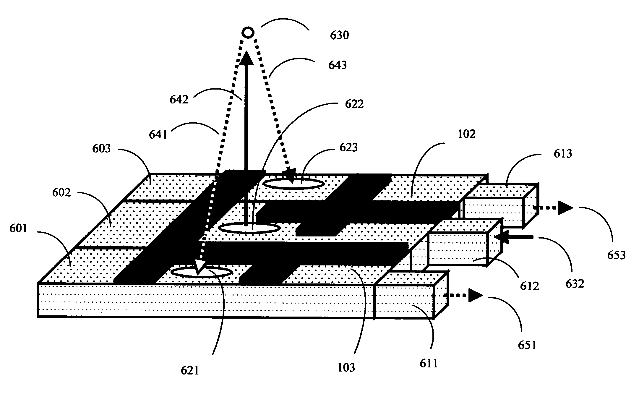
[0046]According to this invention, the main principle that applies throughout is that both sensors in the combined reagent device should be held so close together that both can be simultaneously rehydrated (or hydrated) and activated using a single, unseparated, whole blood drop. Because the two sensors are so close together, however, the system must also be designed to minimize “cross-talk” between the two different neighboring sensors.
[0056]The present invention utilizes these two facts: 1) longer optical paths through whole blood are possible at far-red and near infrared wavelengths, and 2) particles of different size scatter light at different angles; to construct extremely simple dual whole-blood glucose / lipoprotein test strips.
[0062]Table I also shows that side-scattering and low-angle scattering turbidity detectors are also quite useful for whole blood turbidity measurements. The side-scattering geometry has its own set of advantages which tends to compensate for the somewhat more complex side-scattering test-strip design. In particular, note that the 0° angle (no scattering) parameter, shown in Table I, contains important information that can be used to compensate for (normalize) differences in illumination beam intensity. Side scattering designs also allow the sharp fall-off in the narrow angle red blood cell (RBC) scattering signal to be measured (note the Table I results showing that by 20°, the RBC scattering signal is almost zero). Additionally, the fairly large difference in scattering efficiency between the small 0.1 and medium 0.2-micron chylomicron particles at 700 nm and 1000 nm (Table I shows that at 45°, there is about a 2× difference between the 700 and 1000 nm results for 0.2 micron sized particles) can also be detected by use of a side-scattering geometry. This additional information can be used to more accurately estimate the true chylomicron concentration (since chylomicrons vary in size), as well as to better correct for distortion caused by red blood cell interference and other optical interference.
[0063]Thus for each type of test methodology, electrochemical or optical, the multiple test device must be designed to promote rapid access of a small (typically 20 ul or less) sample of whole blood to two different test sensors, and also must be designed to minimize cross-talk between the different test sensors or between the analyte and the red cell background. To the extent that some cross-talk still persists, the meter that reads the reagent may be designed in a way to facilitate the collection of sufficient data, and have sufficient onboard computing means, to do further analysis and mathematical deconvolution in order to accurately separate the two different signals, and distinguish them from background interferences.

Problems solved by technology

As is the case for previous art covering multiple colorimetric reagent pads on a single solid phase support, placing multiple electrically isolated electrochemical cells on a single solid phase support is also unsuitable for small rapid, low cost, analysis of 1-10 ul volume whole blood samples.
Due to the surface tension characteristics of blood, separation of a single 1-10 ul droplet of whole blood into multiple electrically isolated droplets must overcome surface tension effects, and thus is energetically unfeasible without the intervention of energy added by some extra mechanisms.
WO 99 / 58709 discloses dry reagent test devices with two electrochemical sensors, but fails to teach mixed electrochemical / optical devices or pure optical devices.

Method used


Image

  • Dual glucose-turbidimetric analytical sensors
  • Dual glucose-turbidimetric analytical sensors
  • Dual glucose-turbidimetric analytical sensors

Examples


example 1

Combined “Sandwich” Electrochemical Glucose, B-Hydroxybutyrate Sensor with Glucose and Beta-Hydroxybutyrate Electrodes on a First Surface, and a Single Reference Electrode on a Second Surface

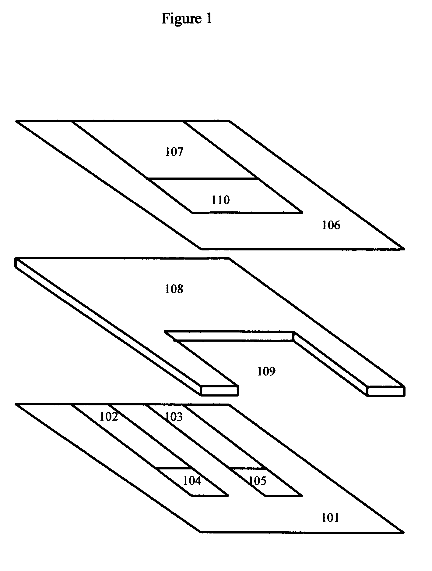
[0074]The “sandwich” design has certain advantages from the user interface perspective. This design acts to “sip” a small drop of blood into an interior cavity formed by the various layers. This helps to partially protect the sample from the outside environment during the reaction.

[0075]Although in examples 1 and 2 given here, glucose oxidase type electrodes are illustrated, it should be understood that the principles taught herein would apply to glucose dehydrogenase type electrodes and electrodes for other enzymatically detected analytes.

Methods:

[0076]A detailed discussion of the methods to construct suitable NADH and Hydrogen peroxide specific electrodes, as well as glucose and hydroxybutyrate specific electrodes, was previously discussed in parent application Ser. No. 10 / 264,206, paragraphs ...

example 2

Multi-Layer Combined Glucose, Beta-Hydroxybutyrate Sensor

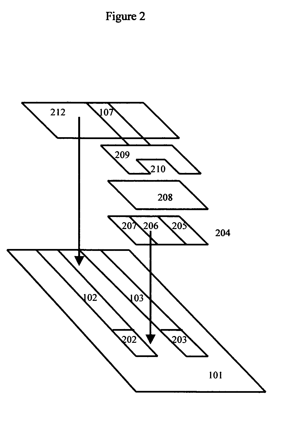
[0088]In an alternative embodiment, a porous spacer layer may be coated on top of the two sensor electrodes, and the reference electrode in turn coated on top of the spacer layer. Because the reference electrode is now elevated a significant distance above the primary support, an elevated stage with a secondary-conducting path may be added. Here a drop of blood is added directly to the primary support.

[0089]This “flat” reagent has its own unique set of advantages. Its more open design facilitates manufacturing. Additionally, some users may prefer applying sample to the more open reagent area.

[0090]This scheme is shown in FIG. 2. In this scheme, conducting electrical paths (102, 103) are laid down on support (101) followed by the glucose and beta-hyroxybutyrate electrodes (202, 203). Usually this is done by a screen-printing process. In subsequent screen-printing processes, porous spacer layer (204) is printed to help fluid flo...

example 3

Optical Combined Glucose / Beta-Hydroxybutyrate (or Other Relevant Second Analyte) Test Strip

[0093]In this example, a blood separating membrane, such as the membranes produced using the highly asymmetric membrane technology of the Filterite division of Pall corporation (“asymmetric polysulfone membranes”, see U.S. Pat. Nos. 4,774,192 and 5,968,836) may be used to conduct the basic reaction. Typically filter membranes rated between 0.8 and 0.2 microns are preferred for this purpose. Asymmetric polysulfone membranes, used in this example, have a variable porosity structure with a large pore side on one side of the membrane, where sample is typically applied, and a small pore side, where the reaction results are typically observed.

[0094]Red cells in the blood sample applied to the large pore side migrate only partially into the membrane matrix, where they become trapped. By contrast, the plasma portion of the blood is free to move all the way to the small pore side. The membrane has suff...


PUM

PropertyMeasurementUnit
volumeaaaaaaaaaa
wavelengthsaaaaaaaaaa
volumeaaaaaaaaaa

Abstract

Diagnostic dry reagent tests capable of reacting with a single drop of whole blood and reporting both glucose and light-scattering analytes, such as chylomicrons, are taught. Such dry reagent tests may employ electrochemical detection methodologies, optical detection methodologies, or both methodologies. These tests alert diabetics to excessive levels of postprandial lipemia caused by meals with excessive amounts of fat, and thus can help reduce the risk of cardiovascular complications in diabetic patients.

Description

[0001]This application is a Continuation in Part of application Ser. No. 10 / 264,206, “Dual glucose-hydroxybutyrate analytical sensors” filed Oct. 3, 2002 now U.S. Pat. No. 6,984,307, which also claimed priority benefit of provisional patent application 60 / 327,535 “Dual glucose-hydroxybutyrate analytical sensors”, filed Oct. 5, 2001.BACKGROUND OF THE INVENTION[0002]1. Field of the Invention[0003]The field of the invention is improved dry reagents for instrumented whole blood tests useful for diabetics.[0004]2. Description of the Related Art[0005]Blood glucose monitoring has revolutionized the treatment of diabetes. Large-scale clinical trials have demonstrated that frequent blood glucose monitoring can aid in the prevention of many of the long-term complications of diabetes, such as diabetic retinopathy, circulatory disorders, and death. After nearly twenty years of development, blood glucose monitoring has now become a several billion dollar a year business.[0006]As the blood glucos...

Claims


Application Information

Patent Timeline
Patent Type & Authority Patents(United States)
IPC IPC(8): G01N27/327G01N21/00C12Q1/00G01N33/52G01N33/66
CPCC12Q1/005C12Q1/006G01N33/523G01N33/66
Inventor ZWEIG, STEPHEN ELIOT
Owner ZWEIG STEPHEN ELIOT
Learn More