
Solid hollow fiber cooling crystallization systems and methods

a technology of solid hollow fibers and crystallization systems, applied in the direction of crystallization plant arrangements, solvent extraction, separation processes, etc., can solve the problems of poor mixing, general disadvantage of msmpr crystallizers, fouling of heat transfer areas, etc., to facilitate effective decoupling of crystal nucleation and crystal growth phenomena, enhance the flexibility and applicability of disclosed devices/systems, and high cooling rates

Inactive Publication Date: 2010-07-13
NEW JERSEY INSTITUTE OF TECHNOLOGY
View PDF24 Cites 3 Cited by
  • Summary
  • Abstract
  • Description
  • Claims
  • Application Information

AI Technical Summary

Benefits of technology

[0011]A further aspect of the present disclosure is directed to solid hollow fiber crystallizer (SHFC) devices / systems for carrying out cooling crystallization of inorganic / organic microsolutes / macrosolutes from a solution, wherein the above-noted shell / housing is in fluid communication with a mixing device / apparatus downstream of the solid hollow fiber crystallizer. Thus, in exemplary embodiments of the present disclosure, the feed solution exits the shell / housing and is fed (in whole or in part) to a mixing device / apparatus. The mixing device / apparatus advantageously functions to further control crystal size distribution.
[0021]A further advantage associated with the systems and methods of the present disclosure is that the disclosed solid hollow fiber cooling crystallizers yield high cooling rates that permit or facilitate effective decoupling of crystal nucleation and crystal growth phenomena and control polymorph formation.

Problems solved by technology

MSMPR crystallizers are generally disadvantaged by poor mixing, fouling of heat transfer areas, small heat transfer area / volume ratio, and problems with scale-up.
Furthermore, these conventional crystallization devices and methods are generally disadvantaged by not being able to meet the targets of a narrow CSD and a small mean crystal size due to imperfect mixing and non-uniform conditions inside the crystallizer.
Conventional cooling crystallization devices are also disadvantaged by both nucleation and crystallization phenomena taking place simultaneously in the same vessel.
In stirred vessels, continuous, batch or semi-batch, nucleation and growth occur in the same device, and therefore high supersaturation levels cannot be used due to severe incrustation of the cooling surfaces with a corresponding loss in performance.
This approach is limited in performance because well-mixed crystallizers are intrinsically inclined towards a spectrum of local conditions in time and space, and consequently a relatively broad CSD.
For example, reverse osmosis has been recognized as a crystallization technique involving solvent removal; however, reverse osmosis is disadvantaged by a high percentage of crystals remaining inside the reverse osmosis module resulting in fouling problems, pore blockage, a decrease in solvent flux, and generation of a supersaturation level with time.
Reverse osmosis is also disadvantaged by the requirement of high operating pressures and the poor solvent resistance of reverse osmosis membranes.
Membrane distillation is another membrane technique involving solvent removal, but is also disadvantaged by fouling and pore blockage.
Membrane distillation is also disadvantaged by a decrease in flux with increased feed concentration, and is generally suitable only for aqueous solutions due to wetting of the hydrophobic membrane pores by organic solvents.

Method used


Image

  • Solid hollow fiber cooling crystallization systems and methods
  • Solid hollow fiber cooling crystallization systems and methods
  • Solid hollow fiber cooling crystallization systems and methods

Examples


examples

Illustrative Example No. 1

KNO3 Crystallization

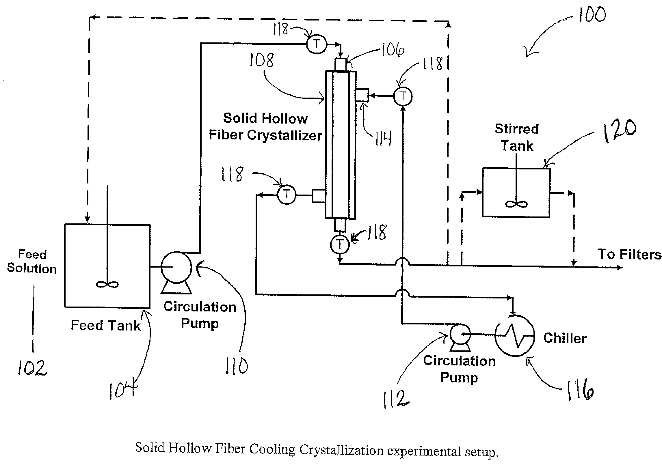
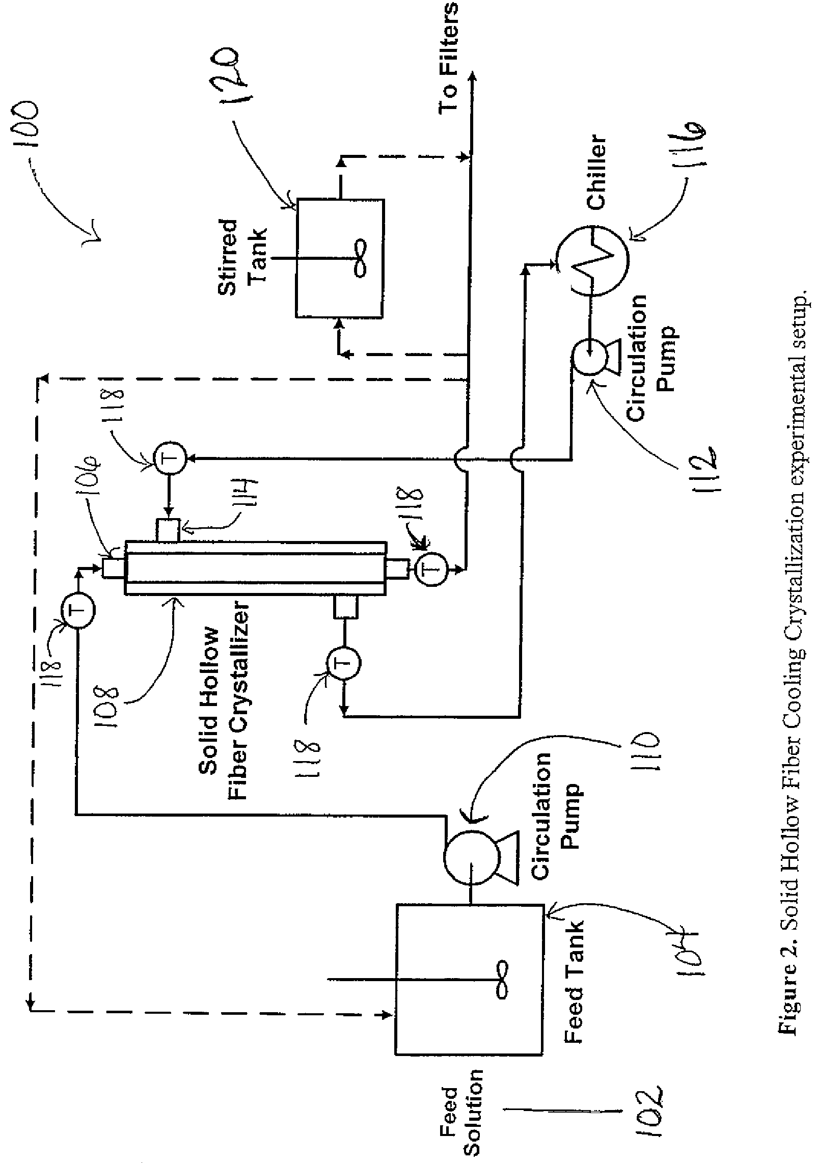
[0097]Aqueous potassium nitrate solutions were prepared by dissolving potassium nitrate (>99%, Sigma Aldrich, St Louis, Mo.) in deionized water. Denatured alcohol (Fisher Scientific Inc., Pittsburgh, Pa.) was used in KNO3 crystal sizing by laser diffraction measurements. Polypropylene solid hollow fibers of 420 / 575 μm ID / OD (Celgard, Charlotte, N.C.) were used for the fabrication of two almost identical modules. Module #1 was fabricated with 35 fibers of 21.9 cm length, while module #2 had the same number of fibers and an active length of 20.3 cm. The experimental setup used is shown in FIG. 2.

[0098]Results obtained with aqueous KNO3 solutions for the SHFC-CST in series and the once through operation modes were compared with those for conventional Mixed Suspension Mixed Product Removal (MSMPR) cooling crystallizers based on literature data13,14. The results for the once through and the feed recycling operation modes are similar and the t...


PUM

PropertyMeasurementUnit
crystallineaaaaaaaaaa
surface area/volume ratioaaaaaaaaaa
diameteraaaaaaaaaa

Abstract

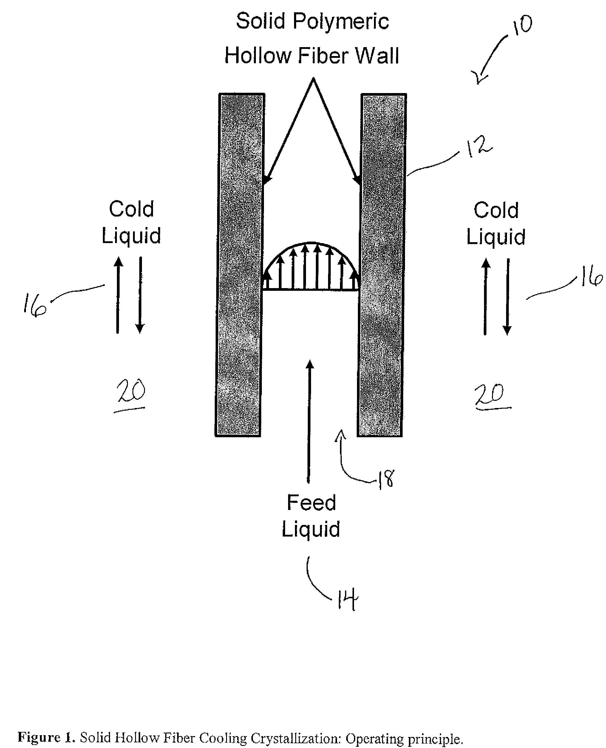
A solid hollow fiber cooling crystallizer and method for crystallizing aqueous and organic solutions are provided. The solid hollow fiber crystallizer (SHFC) for carrying out cooling crystallization of inorganic / organic microsolutes / macrosolutes from solution generally includes a bundle of non-porous hollow fibers mounted within a shell where a feed solution for crystallization flows through the lumen side of the hollow fibers and a cooling solution flows through the shell side to form nuclei and subsequently crystals in the feed solution at a temperature below its saturation temperature. The solid hollow fiber crystallizer may be combined with a mixing device, such as a completely stirred tank or static mixer, to further effectuate crystallization. The solid hollow fiber crystallizer may be operated in a number of modes including feed recycle mode, once through mode, SHFC-in-line static mixer in series mode, and SHFC-CST in series mode. The advantages of solid hollow fiber cooling crystallization in comparison to conventional crystallization processes include improved temperature control between crystallizing solution and coolant, higher nucleation rates, improved control of crystal size and crystal size distribution, smaller crystal size, capability for decoupling crystal nucleation and crystal growth, decreased fouling of process equipment, and improved process scale-up.

Description

CROSS-REFERENCE TO RELATED APPLICATIONS[0001]This patent application is a divisional application and claims the benefit of a commonly assigned, non-provisional U.S. patent application entitled “Solid Hollow Fiber Cooling Crystallization Systems and Methods,” filed Oct. 26, 2005 and assigned Ser. No. 11 / 259,184 now abandoned, which non-provisional patent application claims priority to a co-pending, commonly assigned provisional application entitled “Solid Hollow Fiber Cooling Crystallizer and Method for Crystallizing Aqueous and Organic Solutions,” which was filed on Nov. 8, 2004 and assigned Ser. No. 60 / 625,915. The entire content of the foregoing provisional patent application is incorporated herein by reference.TECHNICAL FIELD[0002]The present disclosure relates to the field of cooling crystallizers. It more particularly relates to cooling crystallizers yielding higher heat transfer area / volume ratio, less fouling, improved temperature control, higher nucleation rates, smaller cry...

Claims


Application Information

Patent Timeline
Patent Type & Authority Patents(United States)
IPC IPC(8): B01D11/00C02F5/00B01D61/00
CPCC30B7/00C30B29/54Y10T117/10Y10T117/1024B01D9/0013B01D9/0059
Inventor SIRKAR, KAMALESH K.ZARKADAS, DIMITRIOS
Owner NEW JERSEY INSTITUTE OF TECHNOLOGY
Learn More