Graphic memory management with invisible hardware-managed page faulting

Inactive Publication Date: 2010-05-04
3DLABS +2
View PDF29 Cites 12 Cited by
  • Summary
  • Abstract
  • Description
  • Claims
  • Application Information

AI Technical Summary

Benefits of technology

[0012]There are different ways to add complexity to a 3D scene. Creating more and more detailed models, consisting of a greater number of polygons, is one way to add visual interest to a scene. However, adding polygons necessitates paying the price of having to manipulate more geometry. 3D systems have what is known as a “polygon budget,” an approximate number of polygons that can be manipulated without unacceptable performance degradation. In general, fewer polygons yield higher frame rates.
[0023]To support this high-speed bus, the Intel specification also provides a special protocol for “AGP memory.” This is not physically separate memory, but just dynamically-allocated system DRAM areas which the graphics chip can access quickly. The Intel chip set includes address translation hardware which makes the “AGP memory” look continuous to the graphics controller. This permits the graphics chip to access large texture bitmaps (e.g. 128 KB) as a single entity.
[0028]As the explosion continues, or as the viewer moves closer to it, its size increases. This effect is produced by scaling the image during the copy. Magnifying the image produces unwanted side effects, however, and the final image may appear blocky and unconvincing. When a texture has more than one color on the interior of the object, as is usually the case, the interior of the scaled texture will also be blocky and unattractive, since there will be no smooth transition between blocks of different color.
[0035]Bit-blit, also written as bit blit and bitblt, is a pixel block copying procedure. The term “bitblt” is short form for “bit block transfer.” One of the most common uses of the bit-blit is in copying pixels from the back framebuffer, where they were written by the graphics processor, to the front framebuffer, from where they will be scanned and displayed. Blitting is also used to simply move a block of pixels from one set of memory locations to another, which effectively moves those pixels on the display, e.g. scrolling of text or moving a window on the screen.
[0039]The apparently-larger virtual texture memory space increases performance as the optimum set of textures (or part of textures) are chosen for residence by the hardware. It also simplifies the management of texture memory by the driver and / or application where either or both try to manage the memory manually. This is akin to program overlays before the days of virtual memory on CPUs where the program had to dynamically load and unload segments of itself.

Problems solved by technology

However, even after these transformations and extensive calculations have been done, there is still a large amount of data manipulation to be done: the correct values for EACH PIXEL of the transformed polygons must be derived from the two-dimensional representation.
The most challenging 3D graphics applications are dynamic rather than static.
Since rendering is a computationally intensive operation, numerous designs have offloaded it from the main CPU.
However, adding polygons necessitates paying the price of having to manipulate more geometry.
Due to the extremely high data rates required at the end of the rendering pipeline, many features of computer architecture take on new complexities in the context of computer graphics (and especially in the area of texture management).
However, this translation is fairly inflexible, and completely out of the user's control.
Thus it cannot be optimized for particular applications, software architectures, or graphics accelerator architectures.
Magnifying the image produces unwanted side effects, however, and the final image may appear blocky and unconvincing.
When a texture has more than one color on the interior of the object, as is usually the case, the interior of the scaled texture will also be blocky and unattractive, since there will be no smooth transition between blocks of different color.
This works within the valid parts of the image, but leaves extremely block edges.
There are three primary artifacts, or defects in the resulting image, caused by bilinear filtering and magnification of the image during copy.
Each of these defects reduce the quality of the resultant image, but are typically unavoidable in present systems.
The first defect is a border effect caused by including some of the key color, which should not be plotted, in the pixels that are valid for plotting.
The second problem is the accuracy with which the cut-out can be performed.
The first method makes the final image too big, while the second method makes it too small.
The third problem is that while bilinear filtering may smooth the color transitions within the selected region of the copy, the edge of the cut-out does not get smoothed and remains blocky.
The present inventor has realized that managing the texture memory in the driver or by the application is very difficult (or impossible) to do properly, because:1. What does the driver / application do when it runs out of memory and needs to fit another texture in?
However, the present inventor has realized that these schemes are ill-suited for most personal computer applications (and many workstation applications).
However, there turns out to be some surprising difficulties in using this idea in computer graphics (especially for texture memory).

Method used


Image

  • Graphic memory management with invisible hardware-managed page faulting
  • Graphic memory management with invisible hardware-managed page faulting
  • Graphic memory management with invisible hardware-managed page faulting

Examples


Embodiment Construction

[0069]The numerous innovative teachings of the present application will be described with particular reference to the presently preferred embodiment (by way of example, and not of limitation).

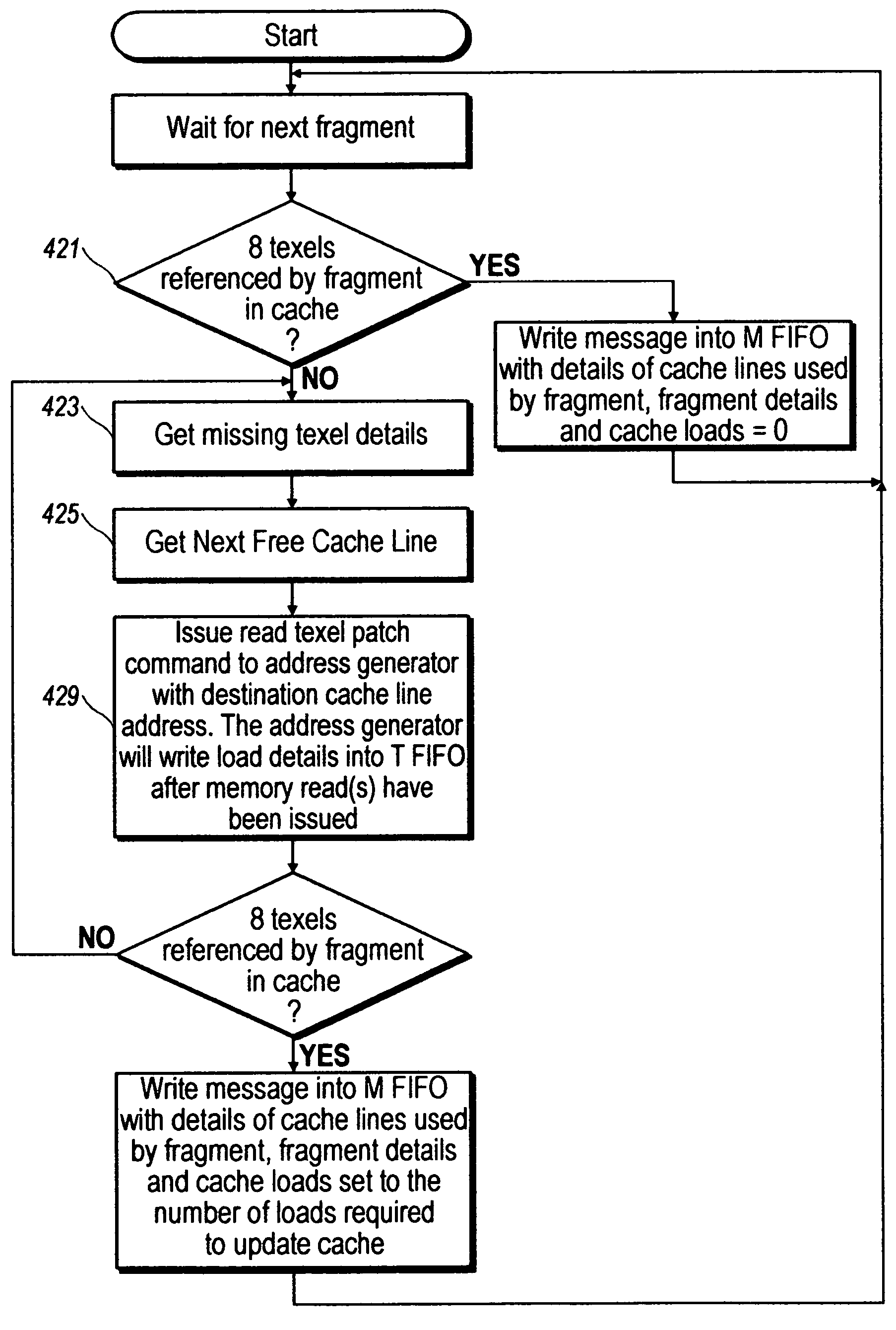
[0070]The following pages give details of a sample embodiment of the preferred rendering accelerator chip (referred to as ‘P3” in the following document, although not all details may apply to every chip revision marketed as P3). Particular attention will be paid to the Texture Read Unit of this chip, where many of the disclosed inventions are implemented. Commonly-owned U.S. application Ser. Nos. 09 / 322,828, 09 / 280,250, and 09 / 266,052 provide various other details of the contexts within which the claimed inventions are most preferably implemented, and are all incorporated herein by reference. The present application is one of nine applications filed simultaneously, which are all contemplated to be implemented together in a common system. The other applications are (U.S. non-provisional applicat...


PUM


Abstract

A computer system in which a graphics accelerator unit manages page faulting of texture data invisibly to the host processor.

Description

BACKGROUND AND SUMMARY OF THE INVENTION[0001]The present application relates to computer graphics rendering systems and methods, and particularly to handling of texture data used by rendering accelerators for 3D graphics.Background: 3D Computer Graphics[0002]One of the driving features in the performance of most single-user computers is computer graphics. This is particularly important in computer games and workstations, but is generally very important across the personal computer market.[0003]For some years the most critical area of graphics development has been in three-dimensional (“3D”) graphics. The peculiar demands of 3D graphics are driven by the need to present a realistic view, on a computer monitor, of a three-dimensional scene. The pattern written onto the two-dimensional screen must therefore be derived from the three-dimensional geometries in such a way that the user can easily “see” the three-dimensional scene (as if the screen were merely a window into a real three-di...

Claims


Application Information

Patent Timeline
IPC IPC(8): G06F13/00G06T11/40G06F12/00
CPCG06T1/60G06T15/04G06F12/1081G09G2360/122G06F12/08G09G2360/121
Inventor BALDWIN, DAVID ROBERT
Owner 3DLABS
Why Eureka
Try Eureka