
Balloon actuator for use in a resectioning device

a technology of resectioning device and balloon, which is applied in the field of resection procedures, can solve the problems of limiting the effective operating range of the device, unable to reach remote areas, and the device may lack sufficient steering and/or flexibility

Inactive Publication Date: 2003-06-19
SCI MED LIFE SYST
View PDF0 Cites 312 Cited by
  • Summary
  • Abstract
  • Description
  • Claims
  • Application Information

AI Technical Summary

Benefits of technology

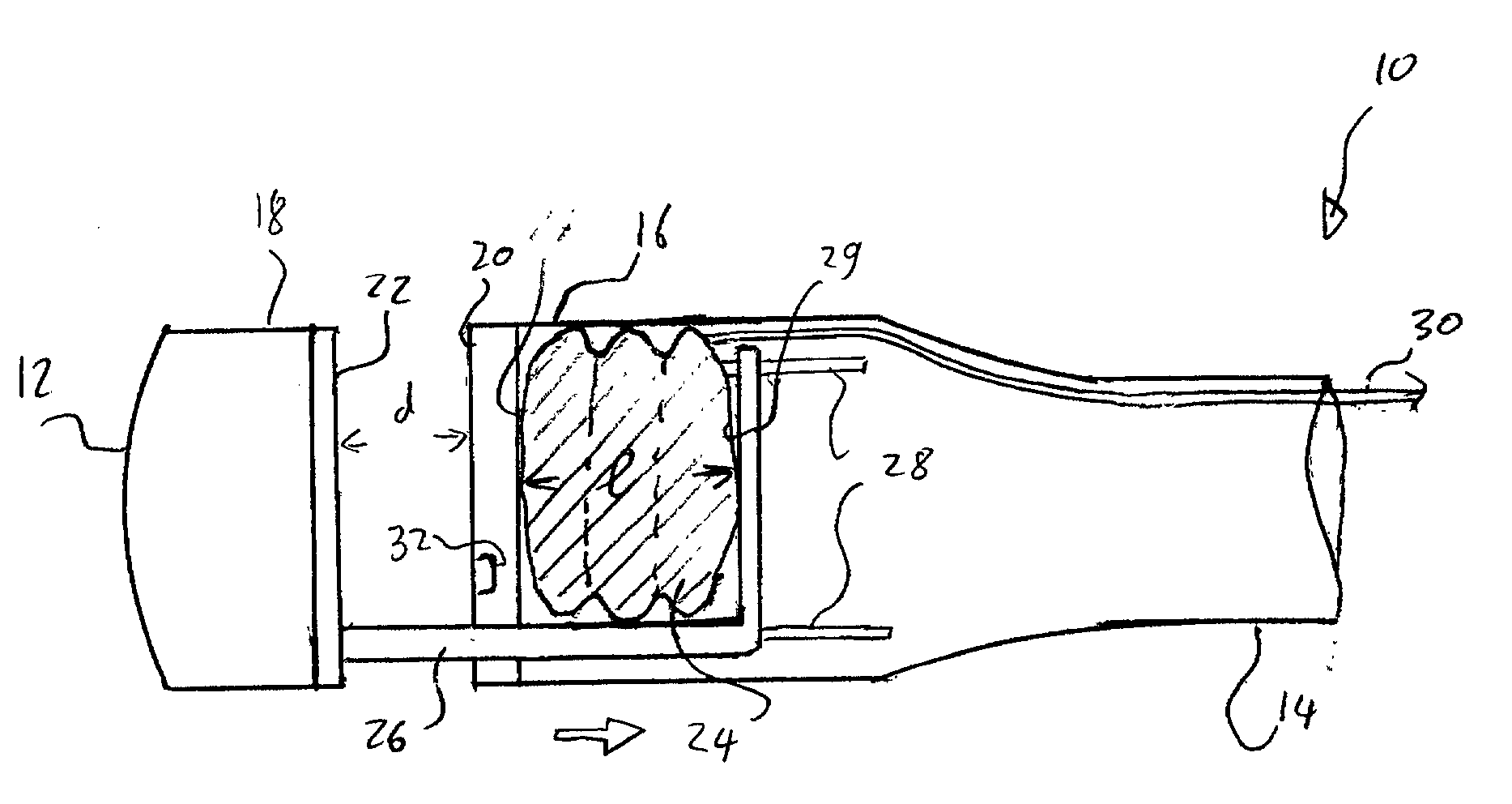
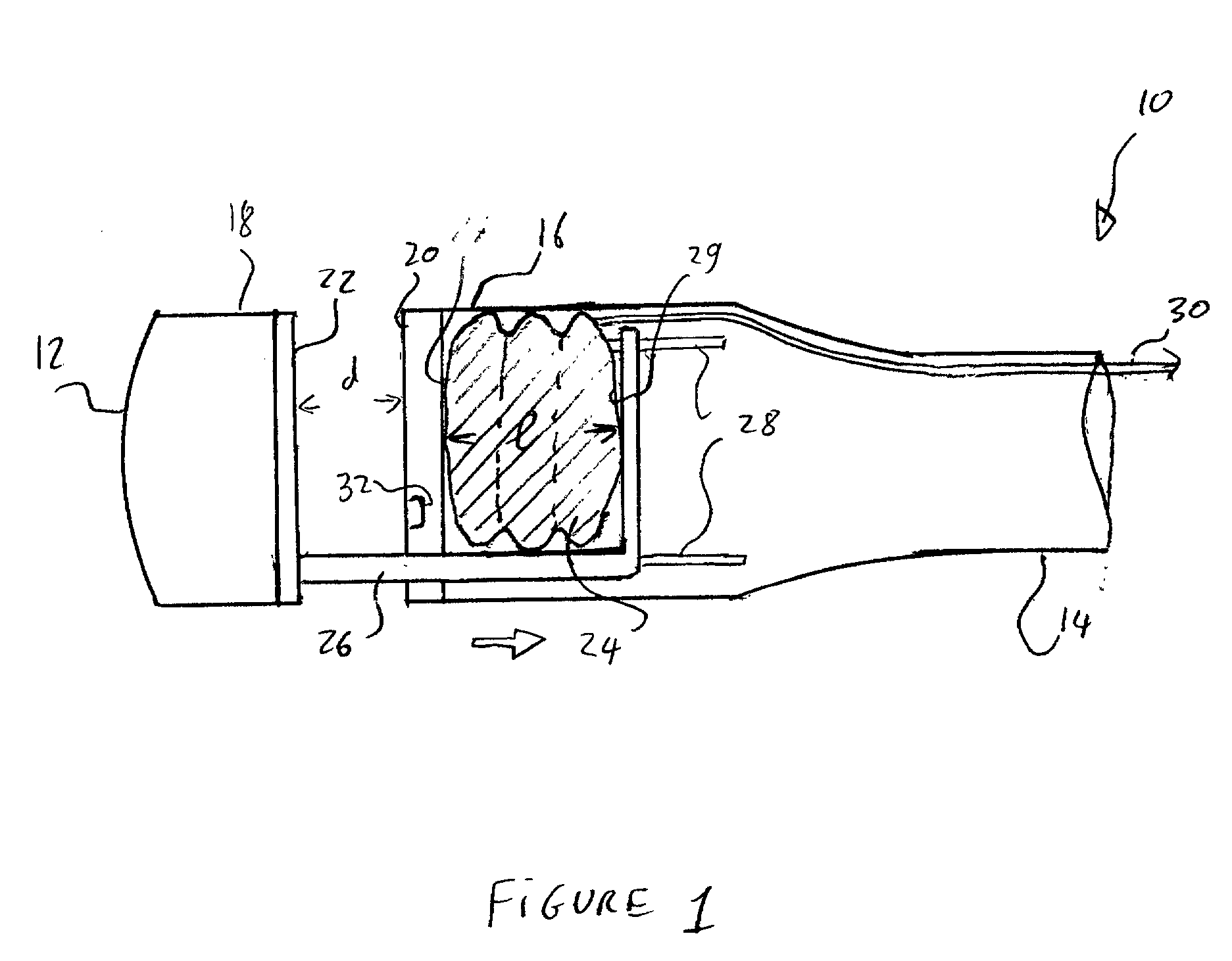
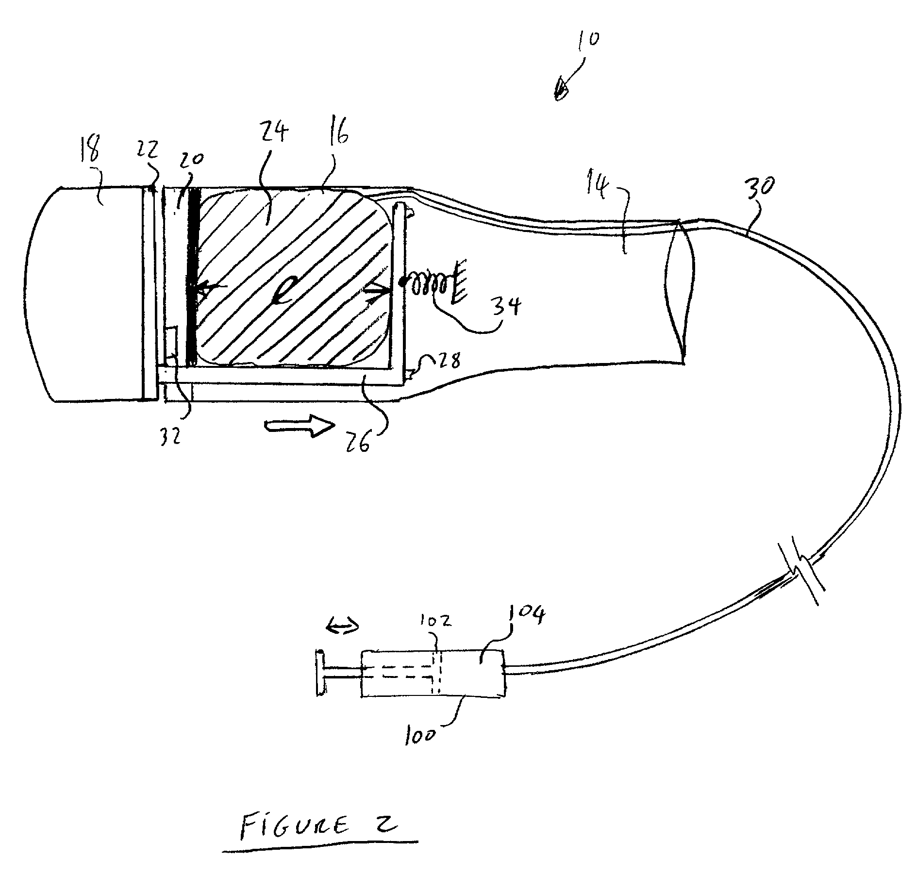
[0016] During insertion of the FTRD 10 into a body lumen, a gap "d" between the anvil portion 18 and the stapler housing 16 is maintained at a minimum closed position to facilitate the insertion. In this closed position, the gap "d" is preferably reduced until the stapler housing 16 contacts the anvil portion 18. Once the device has reached a desired location within the body lumen, the anvil portion 18 is moved relative to the stapler housing 16 to increase the size of the gap "d" until the anvil portion 18 and the stapler housing 16 are in an open, tissue-receiving position with respect to one another.

Problems solved by technology

For example, several known resection devices and procedures require at least one incision in an area near the portion of the organ to be excised to provide access to the lesion or treatment site (because, for example, the resectioning device may lack sufficient steering and / or flexibility).
This arrangement limits the effective operating range of the device as the bending of the shaft into the desired shape before insertion and the rigidity of the shaft once bent require the physician to ascertain the location of the organ section to be removed before insertion, and to deform the shaft accordingly.
Furthermore, the rigidity of the shaft makes it difficult to reach remote areas--particularly those areas which must be reached by winding and / or circuitous routes (e.g., sigmoid colon).

Method used


Image

  • Balloon actuator for use in a resectioning device
  • Balloon actuator for use in a resectioning device
  • Balloon actuator for use in a resectioning device

Examples


Embodiment Construction

[0013] The present invention is an actuator for use in a resectioning device (e.g. a full-thickness resectioning device "FTRD") that uses force generated by an expandable component to operate one or more components of the device. Those skilled in the art will understand that the actuator according to the present invention may be used in conjunction with any resectioning device and that the following examples which describe the use of the actuator(s) in an FTRD are merely illustrative of one possible use. For example, the actuator may be used to open and close an operating head of a resectioning device, by changing a distance between an anvil portion and a stapler housing thereof. Alternatively or additionally, the actuator nay operate a staple firing mechanism and / or the cutting blade of the device.

[0014] With reference to FIG. 1, an FTRD 10 shown in this example includes an anvil portion 18 and a stapler housing 16. The anvil portion 18 defines a distal end 12 of the FTRD 10 which ...


PUM

PropertyMeasurementUnit
Lengthaaaaaaaaaa
Thicknessaaaaaaaaaa
Resilienceaaaaaaaaaa

Abstract

An actuator for a resection device comprises a housing which, when in an operative position, is located within a body lumen of a patient and an inflatable element having a collapsed configuration and an expanded configuration, wherein a characteristic length of the inflatable element is greater when in the expanded configuration than when in the collapsed configuration, a first surface of the inflatable element contacting the housing and a second surface of the inflatable element contacting a moveable component of the device movably coupled to the housing such that changing the configuration of the inflatable element between the expanded and collapsed configurations moves the moveable component relative to the housing in combination with a fluid supply line extending from a distal end connected to the inflatable element to a proximal end which, when the housing is in the operative position, remains outside the body of the patient.

Description

[0001] The present invention relates to resection devices for performing localized resections of lesions in tubular organs. In particular, the invention relates to actuators for the various components for such devices.DESCRIPTION OF RELATED ART[0002] A resection procedure involves excising a portion of an organ and removing the excised tissue. In procedures under which a full thickness section of an organ is removed (i.e., a full-thickness resection procedure), in order to maintain the interior of the organ sealed, tissue surrounding the resected portion must also be bonded together to close the hole created by the resection. Various conventional devices and procedures are available for resectioning lesions in tubular organs.[0003] For example, several known resection devices and procedures require at least one incision in an area near the portion of the organ to be excised to provide access to the lesion or treatment site (because, for example, the resectioning device may lack suff...

Claims


Application Information

Patent Timeline
IPC IPC(8): A61B17/00A61B17/115A61B17/28
CPCA61B17/115A61B2017/2905A61B2017/00539A61B2017/00557
Inventor NUNEZ, GEORGE
Owner SCI MED LIFE SYST
Learn More