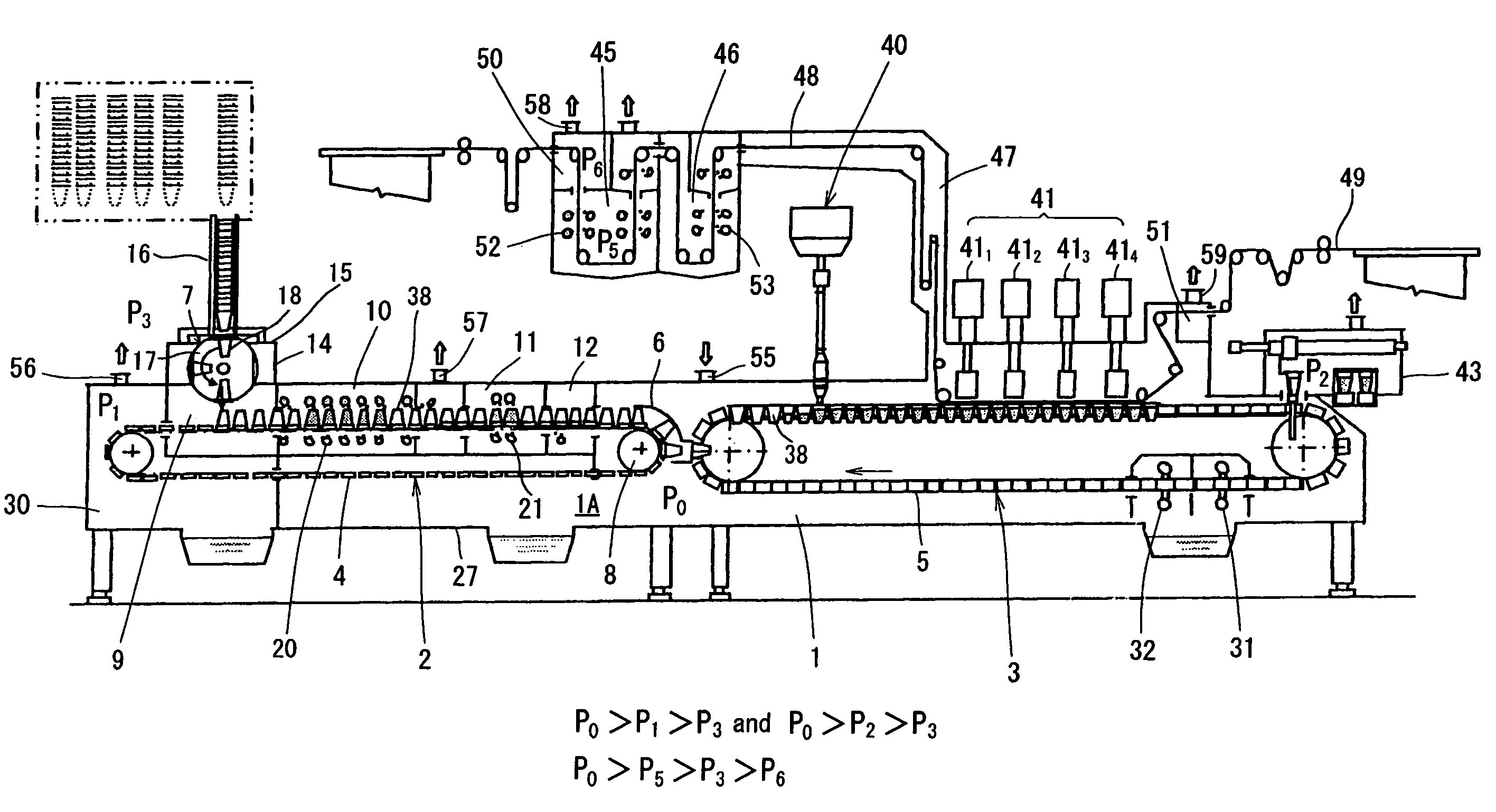
Apparatus for sterilization and filling of cup type container
a container and container body technology, applied in the direction of conveyors, liquid handling, packaging goods types, etc., can solve the problems of difficult to maintain the high level of sterilization, the container cannot be supplied in a stable position, and the transport becomes unstable, so as to achieve effective prevention of penetration of external air into the chamber, good stability, and reliable sterilization
- Summary
- Abstract
- Description
- Claims
- Application Information
AI Technical Summary
Benefits of technology
Problems solved by technology
Method used
Image


Examples
example 1
[0054]The following tests were performed to confirm the effect of aseptic filling by using the above-described aseptic filling apparatus.
[0055]The below-described sample containers were used, cups and lid material having mold adhered thereto were supplied to the aseptic filling apparatus described in the above embodiment, a culture medium was charged under the predetermined conditions, and then the lid material was heat sealed and a sample filled cup product was obtained. The pressure of each chamber in this case was controlled in the below-described manner. The cup product thus obtained was stored for 7 days at a temperature of 30° C. and then turbidity in the culture medium and the flocculation were visually evaluated. The evaluation results demonstrated that no turbidity or flocculation was present in the culture medium and the possibility of manufacturing an aseptic product was confirmed.
1. Sample Container
[0056](1) Sample cup: 200 mL, PET cup (mouth diameter 75 mm, height 108.5...
PUM
| Property | Measurement | Unit |
|---|---|---|
| height | aaaaa | aaaaa |
| height | aaaaa | aaaaa |
| air pressure | aaaaa | aaaaa |
Abstract
Description
Claims
Application Information
 - R&D
- Intellectual Property
- Life Sciences
- Materials
- Tech Scout
- Unparalleled Data Quality
- Higher Quality Content
- 60% Fewer Hallucinations
Browse by: Latest US Patents, China's latest patents, Technical Efficacy Thesaurus, Application Domain, Technology Topic, Popular Technical Reports.
© 2025 PatSnap. All rights reserved.Legal|Privacy policy|Modern Slavery Act Transparency Statement|Sitemap|About US| Contact US: help@patsnap.com