
Manufacturable sampled grating mirrors

a technology of grating mirrors and sampled grating, which is applied in the direction of lasers, semiconductor lasers, optical resonator shapes and construction, etc., can solve the problems of compromising output power, unable to meet the potential of light-based systems, and designs that can provide over 40 nm tuning range have not been able to provide much more than a couple of milliwatts of power, etc., to achieve wide tuning, simple manufacturing, and large wavelength span

Inactive Publication Date: 2010-01-05
LUMENTUM OPERATIONS LLC
View PDF17 Cites 3 Cited by
  • Summary
  • Abstract
  • Description
  • Claims
  • Application Information

AI Technical Summary

Benefits of technology

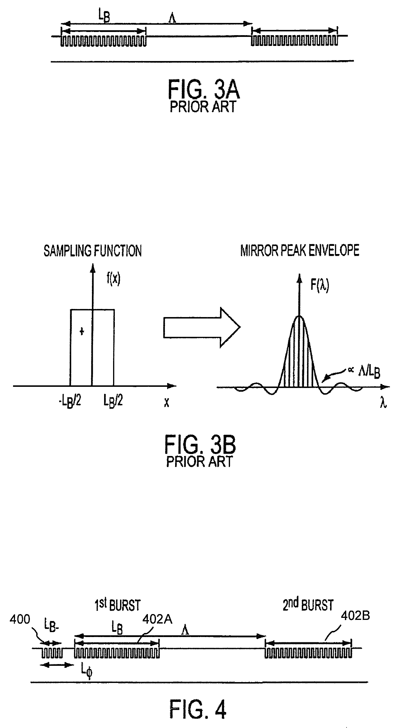
[0035]This invention relates to the tailoring the reflectivity spectrum of a SGDBR by applying digital sampling theory to choose the way each mirror is sampled. The resulting mirror covers a larger wavelength span and has peaks with a larger, more uniform, coupling constant (κ) than the mirrors produced using conventional approaches. The improved mirror also retains the benefits of the sample grating approach. These embellishments on the SGDBR design provide devices that meet the higher power goals with wide tuning. In addition, most of the embodiments are relatively simple to manufacture.

Problems solved by technology

Thus, while diode lasers have provided solutions to many problems in communications, sensors and computer system designs, they have not fulfilled their potential based on the available bandwidth afforded by light-based systems.
In addition, widely tunable semiconductor lasers, such as a sampled-grating distributed-Bragg-reflector (SGDBR) laser, a grating-coupled sampled-reflector (GCSR) laser, and vertical-cavity surface emitting lasers with micro-electromechanical moveable mirrors (VCSEL-MEMs) generally must compromise their output power in order to achieve a large tuning range.
Designs that can provide over 40 nm of tuning range have not been able to provide much more than a couple of milliwatts of power out at the extrema of their tuning spectrum.
Such powers are available from DFB lasers, but these can only be tuned by a couple of nanometers by adjusting their temperature.
It is impossible to simultaneously maximize all three of the above specifications using a SG-DBR, as improving one specification worsens the others.
The sampled grating approach is limited largely by the fact that the unsampled grating κ is technologically limited by optical scattering to around 300 cm−1.
Another limiting factor is that the reflectivity of the multi-peaked mirror falls off at the outer peaks, along with the gain.
This duty ratio, however, is inversely proportional to the wavelength range the multi-peaked SG mirror can effectively cover, which limits the tuning range of a SG-DBR laser.

Method used


Image

  • Manufacturable sampled grating mirrors
  • Manufacturable sampled grating mirrors
  • Manufacturable sampled grating mirrors

Examples


Embodiment Construction

[0046]In the following description, reference is made to the accompanying drawings which form a part hereof, and in which is shown, by way of illustration, an embodiment of the present invention. It is understood that other embodiments may be utilized and structural changes may be made without departing from the scope of the present invention.

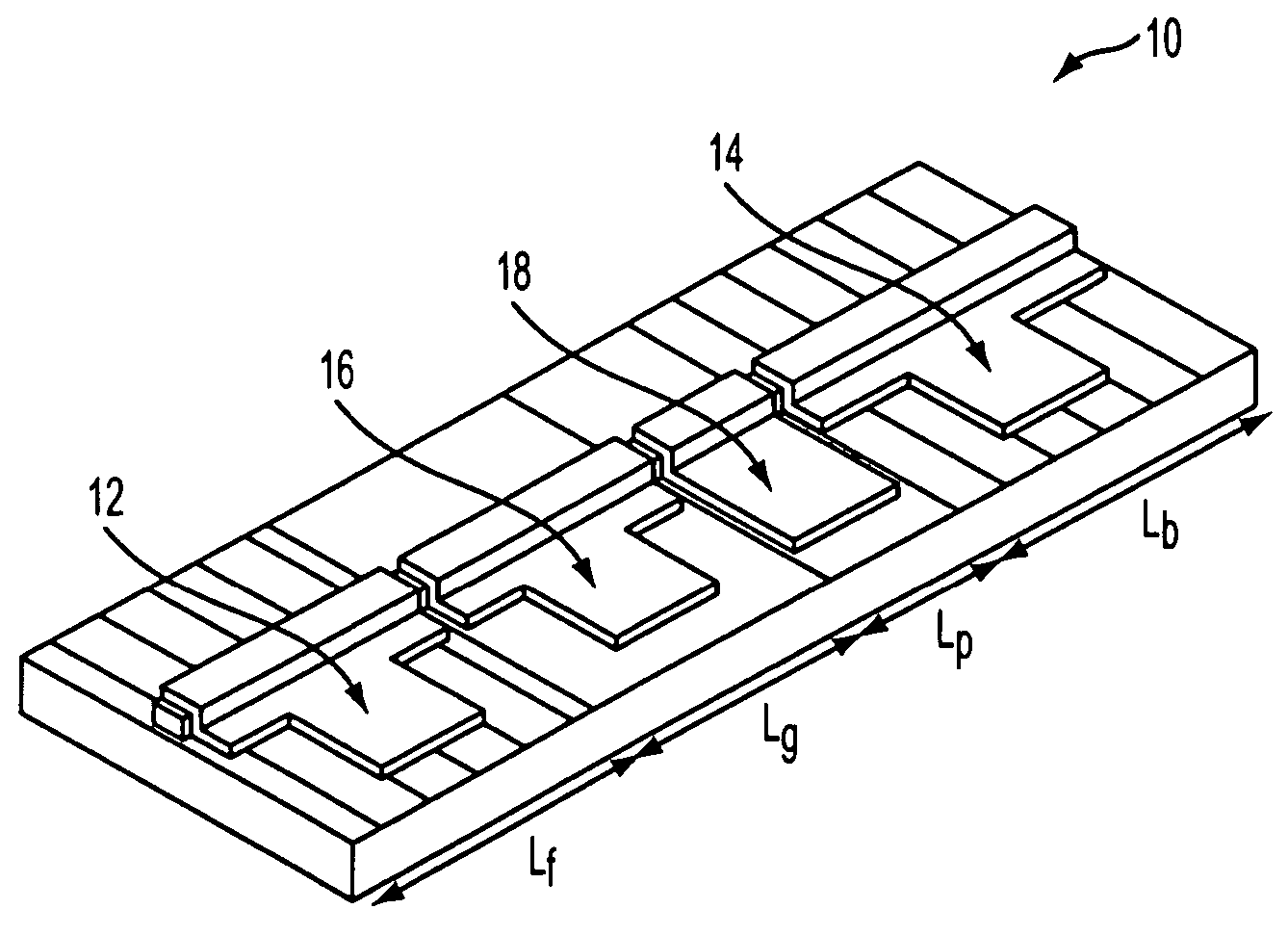
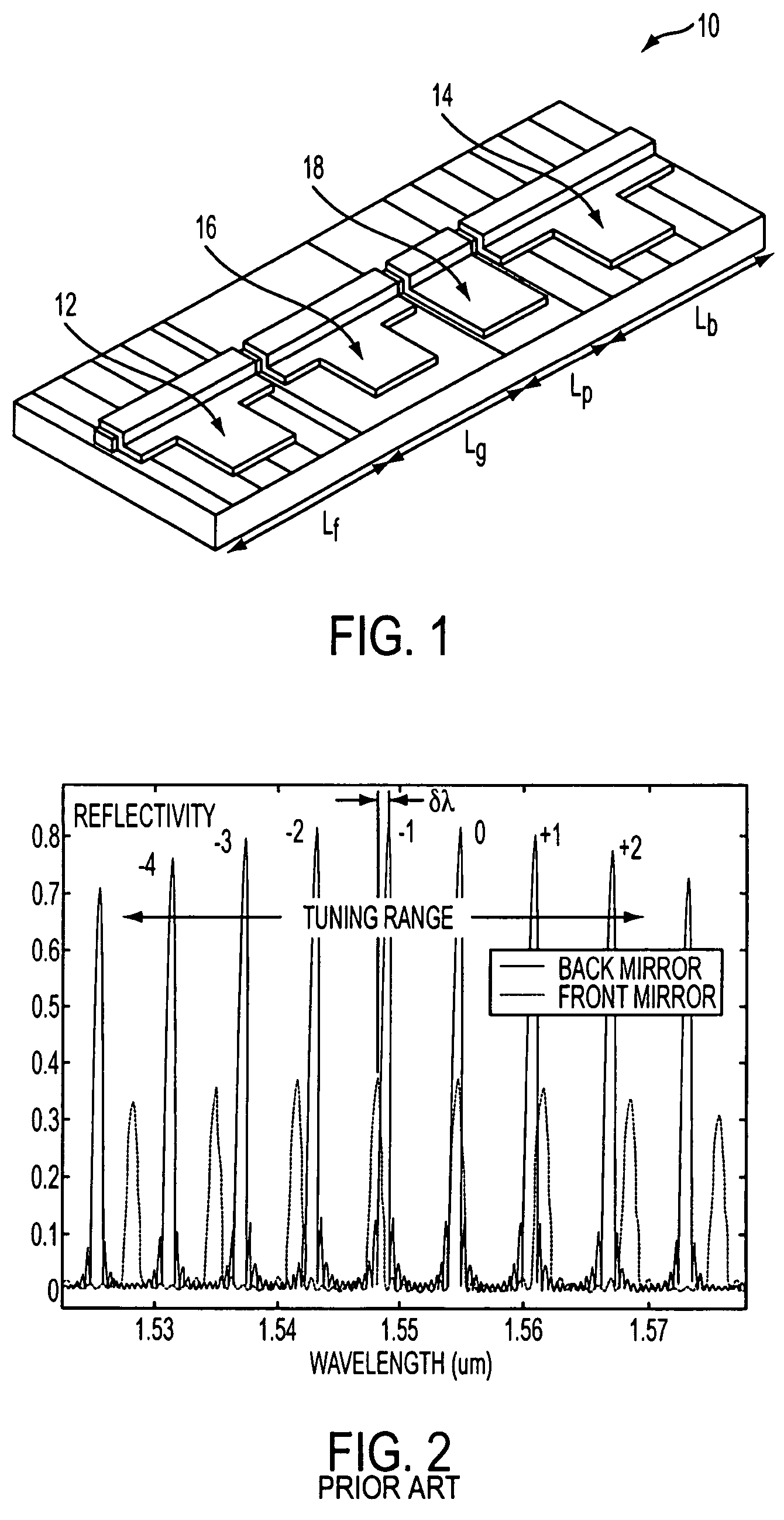
[0047]FIG. 2 depicts a widely-tunable, four-section SG-DBR laser 10 that makes use of two multi-peaked DBR mirrors 12,14, which are formed and configured in accordance with the present invention, to achieve an extended tuning range. Currents are applied to the various electrodes to provide a desired output optical power and wavelength as discussed in U.S. Pat. No. 4,896,325. As described therein, a current to the gain section 16 creates light and provides gain to overcome losses in the laser cavity, currents to the two differing SG-DBR wavelength-selective mirrors 12,14 are used to tune a net low-loss window across a wide wavelength range to se...


PUM


Abstract

The present invention relates to the tailoring the reflectivity spectrum of a sampled-grating distributed Bragg reflector (SGDBR) by applying digital sampling theory to choose the way each reflector is sampled. The resulting mirror covers a larger wavelength span and has peaks with a larger, more uniform, coupling constant (κ) than the mirrors produced using conventional approaches. The improved mirror also retains the benefits of the sample grating approach. Additionally, most of the embodiments are relatively simple to manufacture.

Description

CROSS-REFERENCE TO RELATED APPLICATIONS[0001]This application is a divisional application under 35 U.S.C. Section 121 of the following and commonly-assigned U.S. utility patent application: Ser. No. 09 / 879,821, filed Jun. 11, 2001, now U.S. Pat. No. 6,937,638 by Gregory A. Fish and Larry A. Coldren, entitled “IMPROVED, MANUFACTURABLE SAMPLED GRATING MIRRORS,”which application claims the benefit under 35 U.S.C. Section 119(e) of the following and commonly-assigned U.S. provisional patent application: Ser. No. 60 / 210,612, filed Jun. 9, 2000, by Gregory A. Fish and Larry A. Coldren, entitled “IMPROVED, MANUFACTURABLE SAMPLED GRATING MIRRORS,”both of which applications are incorporated by reference herein.[0002]This application is related to the following and commonly-assigned U.S. utility patent applications:[0003]Ser. No. 09 / 614,224, filed Jul. 12, 2000, by Larry A. Coldren et al., and entitled “METHOD OF MAKING A TUNABLE LASER SOURCE WITH INTEGRATED OPTICAL AMPLIFIER,” now U.S. Pat. ...

Claims


Application Information

Patent Timeline
Patent Type & Authority Patents(United States)
IPC IPC(8): H01S3/08H01S5/0625H01S5/12H01S5/125
CPCB82Y20/00H01S5/125H01S5/1209H01S5/06256
Inventor FISH, GREGORY A.COLDREN, LARRY A.
Owner LUMENTUM OPERATIONS LLC
Learn More