
Nanoengineered membranes for controlled transport

a technology of controlled transport and nanoengineered membranes, applied in the direction of catalyst activation/preparation, metal/metal-oxide/metal-hydroxide catalysts, chemical/physical processes, etc., can solve the problems of significant concentration difference, significant challenge and opportunity, and significant challenges, and achieve the effect of printing on even smaller scales

Inactive Publication Date: 2010-01-05
UT BATTELLE LLC
View PDF11 Cites 35 Cited by
  • Summary
  • Abstract
  • Description
  • Claims
  • Application Information

AI Technical Summary

Benefits of technology

The invention is a membrane that can be used to control the transport of materials. It consists of a substrate and a cover, with a channel in between them. The membrane has a plurality of fibers that are positioned in the channel and are aligned within 45 degrees of perpendicular to the surface of the substrate. The fibers can be carbon nanofibers, metal nanofibers, or plastic nanofibers. The membrane can be used to control material transport by using chemical derivatives or coatings on the fibers, or by using electrical driving forces. The membrane can be used to mimic biological cells, allowing for chemical reactions to be localized and controlled in a mesoscale object. The invention also allows for the construction of joined cellular structures capable of chemical communication, with artificial, electronic-based control mechanisms.

Problems solved by technology

Also, the small fluid volume of a cell allows for only a few thousand molecules to result in a significant concentration difference.
Therefore, a significant challenge and opportunity exists in the construction of components with engineered features on multiple length scales that scale six orders of magnitude (nm. to mm
However, just as creating structures on the scale of natural systems presents great opportunities, it also presents significant challenges.
The most significant challenge in mimicking cell structures is fabricating appropriate membrane structures that contain molecular-scale pores.
This method can confine membrane components to specific grid elements but does not result in fluid filled cells of practical utility as the planar supported membranes rest on only a 10-20 Å thick aqueous layer.
However, the design of discrete, joined cells with specific pore structures is not obvious with this approach.
Additionally, the long-term stability of such structures may preclude their use in practical applications.
However, as with the lipid bilayers discussed above, these structures are planar in format and do not lend themselves to the design of discrete, fluidly joined cells.
This can considerably limit the rate at which material can transfer across a membrane potentially limiting chemical transfer rates compared to natural cell membranes.
In general, the limitations of conventional micromachining techniques prevent constructing such structures with molecular dimensions.
However, these techniques only allow for a limited control of nanowire position and morphology on a larger scale.

Method used


Image

  • Nanoengineered membranes for controlled transport
  • Nanoengineered membranes for controlled transport
  • Nanoengineered membranes for controlled transport

Examples


example 1

Synthesis of Deterministically Grown Carbon Nanofibers

[0060]The inventors of the present application have developed methods for catalytically controlled growth of vertically aligned (i.e., perpendicular to the substrate surface), multi-walled carbon nanofibers (see Merkulov et al. articles referenced above). The basic process utilizes plasma-enhanced chemical vapor deposition (PE-CVD) in conjunction with E-beam lithography for the precise placement of evaporated and size-controlled catalyst-metal dots. A mixture of acetylene (C2H2) and ammonia (NH3) is used as a source gas during the PE-CVD process. The substrate is heated above approximately 600° C. After the plasma is turned on, carbon nanofibers grow selectively at the locations where catalyst dots (Ni, Fe, Co) were pre-deposited. The procedure is outlined in FIG. 1, and Example 5 below describes one method that has been used to produce vertically aligned multi-walled carbon nanofibers. This method is similar to the hot-filament ...

example 1a

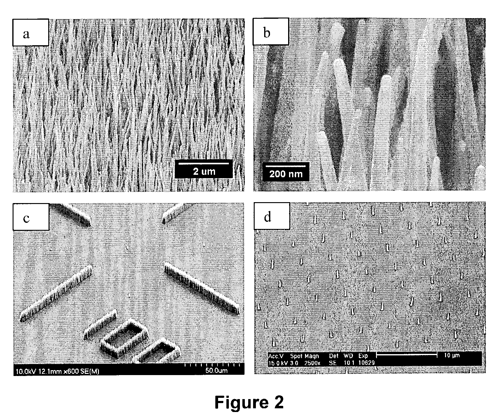
[0061]Examples of carbon nanofibers grown from lithographically defined catalyst dots are shown in FIG. 2. FIGS. 2a-c shows images of carbon nanofibers (CNFs) grown as “chaotic forests”. The CNFs were grown from catalytic metal particles that are randomly distributed on the surface. The metal particles are seen at the tips of the fibers in FIGS. 2a and b. After growth of the fibers, these catalytic particles can also be removed.

[0062]When VACNFs are grown chaotically, there is less control of the relative location of catalyst nanoparticles, or the size of the particles. However, these chaotic forests of VACNFs can be grown in lithographically defined areas as seen in FIG. 2c. Alternatively, VACNFs can be prepared in a completely deterministic fashion by precise patterning of the catalyst metal particle. In this approach, the patterning of the particles determines the VACNF location, the size of the catalyst particle defines the diameter of the VACNF, and growth time determines the l...

example 2

Fabrication of Addressable Electrochemical Nanofiber Probe Arrays

[0063]A fabrication technique has been developed that provides multielement nanoscale probing arrays with each fiber element featuring independent addressability, and an exposed electrochemically active tip of approximately 20-30 nanometer diameter (FIG. 4) (See Guillorn et al., “Individually addressable vertically aligned carbon nanofiber-based electrochemical probes”, J. Appl. Phys., 91(6), 3824-3828, 2002). These devices may be fabricated on traditional Si wafers, or upon quartz wafers, facilitating their use upon fluorescent microscopy platforms. Tungsten interconnects provide wirebond connectivity to individual elements of fibers that are deterministically grown at the opposing terminus of tungsten leads. The entire structure (interconnects and fiber sheath) is passivated with a high-quality oxide, such that electrochemical activity is limited to only the extreme exposed tip of each fiber element. These native car...


PUM

PropertyMeasurementUnit
widthaaaaaaaaaa
diametersaaaaaaaaaa
lengthaaaaaaaaaa

Abstract

A nanoengineered membrane for controlling material transport (e.g., molecular transport) is disclosed. The membrane includes a substrate, a cover defining a material transport channel between the substrate and the cover, and a plurality of fibers positioned in the channel and connected to and extending away from a surface of the substrate. The fibers are aligned perpendicular to the surface of the substrate, and have a width of 100 nanometers or less. The diffusion limits for material transport are controlled by the separation of the fibers. In one embodiment, chemical derivatization of carbon fibers may be undertaken to further affect the diffusion limits or affect selective permeability or facilitated transport. For example, a coating can be applied to at least a portion of the fibers. In another embodiment, individually addressable carbon nanofibers can be integrated with the membrane to provide an electrical driving force for material transport.

Description

STATEMENT REGARDING FEDERALLY SPONSORED RESEARCH[0001]This invention was made with Government support under Contract No. DE-AC05-00OR22725 awarded to UT-Battelle, LLC, by the U.S. Department of Energy. The Government has certain rights in this invention.CROSS-REFERENCES TO RELATED APPLICATIONS[0002]Not Applicable.BACKGROUND OF THE INVENTION[0003]1. Field of the Invention[0004]The invention relates to the use of nanofibers as membranes for controlling molecular transport. These devices provide nanoscale control of molecular transport by mimicking biological cellular membranes. Semi-permeable membranes can be created from the directed self-assembly of nanofibers, allowing for the passage of molecules smaller than the wall-to-wall spacing of the nanofibers. The diffusion limits can be controlled by the separation of the fibers, both laterally and along the direction of transport. Chemical potential gradients can be engineered and used to direct transport. These membranes can involve ch...

Claims


Application Information

Patent Timeline
Patent Type & Authority Patents(United States)
IPC IPC(8): B01D63/00B01D67/00B01D69/02B01D71/02B01J23/755B01J35/00B01J37/34G01N27/40
CPCB01D67/0072B01D67/0093B01D69/02B01D69/141B01D71/021B01J23/755B01J35/0013B01J37/34B01D67/0088Y10S977/705B01D2325/10B82Y30/00B01D2323/30Y10S977/962Y10S977/92Y10S977/906Y10S977/701Y10S977/706Y10S977/747Y10S977/704Y10S977/745Y10S977/746Y10S977/789B01D69/14111B01J35/45B01J35/23
Inventor DOKTYCZ, MITCHEL J.SIMPSON, MICHAEL L.MCKNIGHT, TIMOTHY E.MELECHKO, ANATOLI V.LOWNDES, DOUGLAS H.GUILLORN, MICHAEL A.MERKULOV, VLADIMIR I.
Owner UT BATTELLE LLC
Learn More