Low visibility, fixed-tune, wide band and field-diverse antenna with dual polarization

a dual-polarization, low-visibility technology, applied in the direction of non-resonant long antennas, antenna details, antennas, etc., can solve the problems of destructive interference, limited power and duration of power supply, and often subject to vandalism or other unwanted attention of antennas, so as to achieve reliable transmission and reception characteristics

Active Publication Date: 2009-12-29
LAIRD CONNECTIVITY INC
View PDF22 Cites 5 Cited by
  • Summary
  • Abstract
  • Description
  • Claims
  • Application Information

AI Technical Summary

Benefits of technology

[0019]The low visibility, field-diverse, and fixed-tune radio antenna of the present invention transmits its signals using dual polarization to obtain field diversity. A generally small (on the order of a few inches), thin and flat shape, and rectangular printed circuit board is wrapped with conducting foil or the like with plated-through holes providing conduction between the two large flat sides of the rectangle. The antenna is wound about the substrate for a preferred resonant frequency. Alternatively, foil can be laid in between offset plated-through holes in order to obtain the helix configuration. The plated-through holes provide easy means by which such an antenna can be fabricated as upon application of the antenna foil, the margin of the substrate external to the plated-through holes can be removed by sawing, routing, or stamping.
[0020]The flat helix configuration may be square or rectangular in shape and delivers a field-diverse transmission signature that diminishes Raleigh fading, signal fading, and dead spots. The dimensions of the resulting field-diverse antenna are important, as they establish the base resonant frequency about which the antenna will naturally resonate. A radome enclosure is used to encapsulate and cover the antenna and may serve to camouflage or disguise the antenna so that it attracts less attention and will be less subject to vandalism or mischief. The radome may be cylindrical or rectangular in nature according to the dimensions of the enclosed antenna. Industry standard mounts can be used in conjunction with the constant impedance section to eliminate the need for impedance matching or allow convenient attachment of alternative or additional impedance matching networks. In the embodiment described herein, elevation of the antenna somewhat above the ground plane lowers the radiation angle.
[0022]In one embodiment of the present invention, a low-visibility, fixed-tune, wideband, and field-diverse antenna for providing communications has an antenna-supporting core having a width and a length, and an antenna that is continuous conductively wrapped upon the core in a manner for a selected resonant frequency. The antenna radiates in a diverse manner with the horizontal and vertical field components of a field radiated by the antenna being substantially in phase and not circularly polarized. In this way, a low-visibility, field-diverse antenna is realized having helical antenna characteristics without severe circular polarization radiation. This promotes a modern, futuristic, and disguised look for reliable communications.
[0023]In another embodiment of the present invention, a low-visibility, wideband, and field-diverse antenna that is fixed-tune has a first transmission line coupled to an input. A second transmission line is coupled to the first transmission line with a shunt capacitor system coupled to the first and second transmission lines. A third transmission line is coupled to the second transmission line such that the low-visibility, wideband, and field-diverse antenna is fixed-tune, enables reliable transmission and reception characteristics in a repeatably manufacturable manner. These characteristics of the resulting antenna generally arise from the resonance traits of one or more of the three transmission lines.

Problems solved by technology

Particularly with cellular telephones, the power supply for the antenna associated with the cellular phone is provided by a battery and is consequently limited in power and duration of the power supply.
Such easy access makes such antennas often subject to vandalism or other unwanted attention.
In the art, it is known that destructive interference occurs when reflected signals destructively interfere with transmitted signals.
This is known as Raleigh fading and creates signal fading or dead spots that inhibit or diminish the desired communications for which cellular phones and the like are intended.
However, at higher frequencies, wider bandwidths are required and the narrow bandwidth of such antennas prevent them from being used at such higher frequencies.
This change of direction of radiation from broadside to endfire is generally impractical for mobile and portable applications.
Such high directivity and such an unfavored angle of radiation impose certain inconveniences and limitations upon small transmitters and their antennas.

Method used


Image

  • Low visibility, fixed-tune, wide band and field-diverse antenna with dual polarization
  • Low visibility, fixed-tune, wide band and field-diverse antenna with dual polarization
  • Low visibility, fixed-tune, wide band and field-diverse antenna with dual polarization

Examples


Embodiment Construction

)

[0033]The detailed description set forth below in connection with the appended drawings is intended as a description of presently-preferred embodiments of the invention and is not intended to represent the only forms in which the present invention may be constructed and / or utilized. The description sets forth the functions and the sequence of steps for constructing and operating the invention in connection with the illustrated embodiments. However, it is to be understood that the same or equivalent functions and sequences may be accomplished by different embodiments that are also intended to be encompassed within the spirit and scope of the invention.

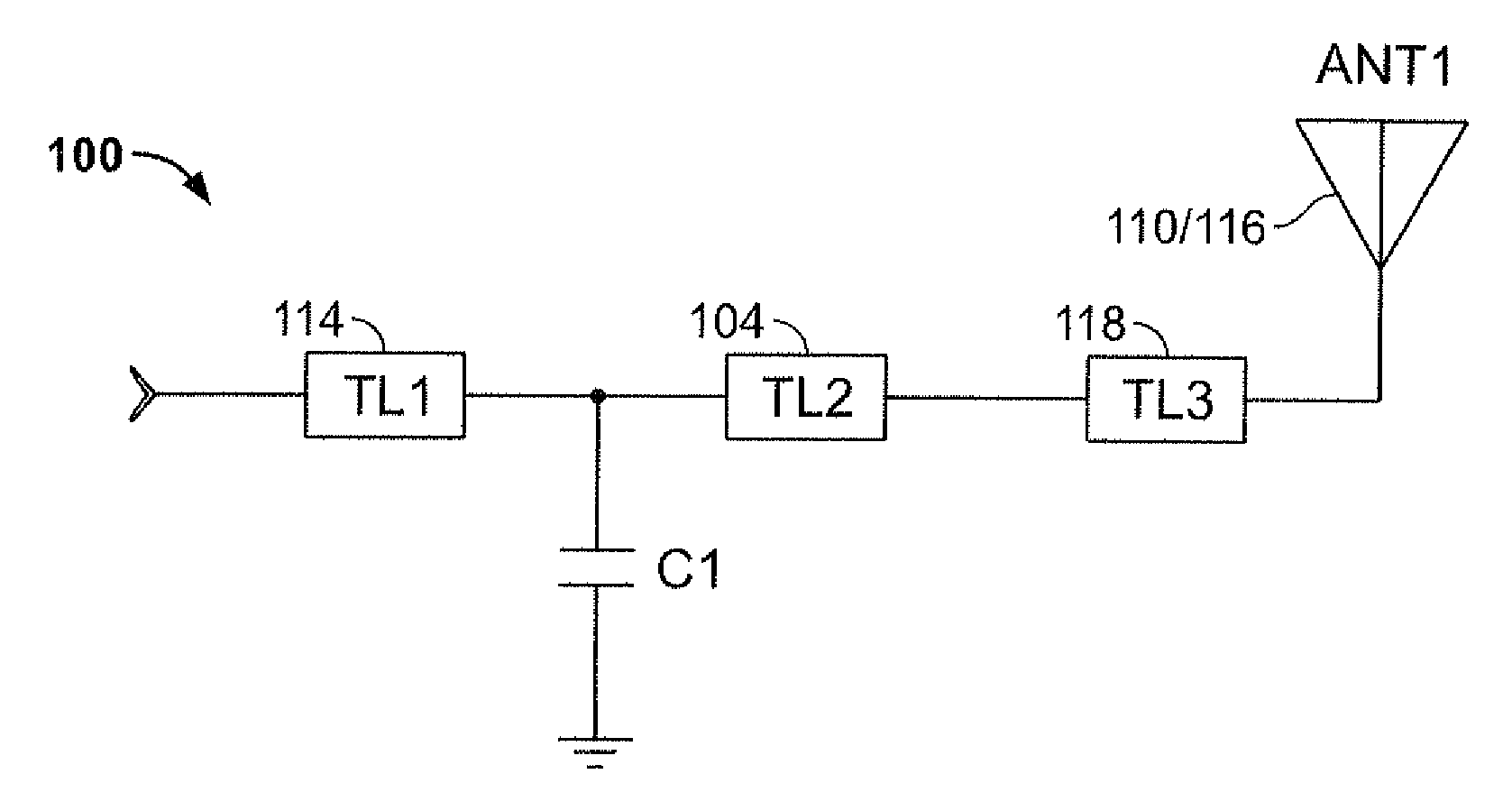
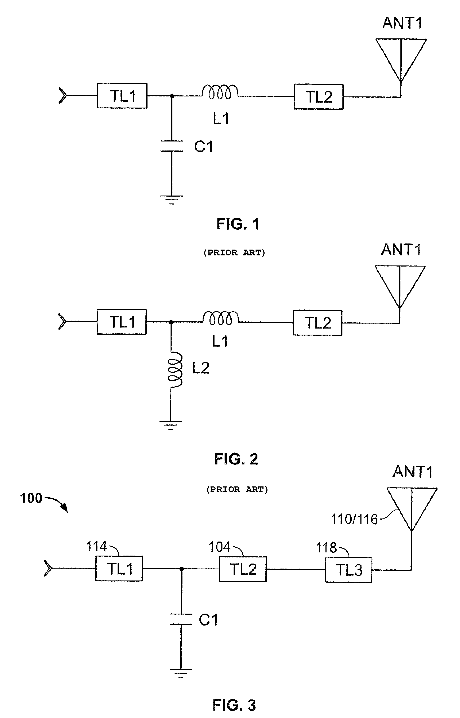
[0034]Referring to the drawings where like numerals of reference designate like elements throughout it will be noted that the present invention provides means by which small, low-power antennas can achieve better signal transmission and power efficiencies while avoiding intentional, mischievous destruction.

[0035]FIGS. 1 and 2 show sche...


PUM


Abstract

A low-visibility, fixed-tune, wideband, and field-diverse antenna provides cross-polarized fields enhancing signal communications but having helical antenna characteristics without severe circular polarization radiation thereby promoting a modern, futuristic, and disguised look for reliable communications. A generally flat, but helical, antenna is achieved in conjunction with a core substrate about which the antenna is wrapped, wound, or fixed. The core substrate, pitch or angle of the helix, length of the transmitting antenna, and copper traces thickness are chosen for a specific resonant frequency range. The length and width of the helix are chosen in order to dimension the helical antenna between its linear and circular polarization modes to thereby deliver field-diverse and cross-polarized transmission modes. In order to optimize the manufacturing process, holes may be created within the substrate. These holes are plated with conducting material so that conducting foil on opposite faces of the substrate may be electrically connected. The holes may be offset according to the pitch of the helix. Once the transmitting antenna has been fabricated upon the core substrate, the margin between the plated-through holes and the edge of the substrate may be separated by cutting, sawing, or stamping.

Description

COPYRIGHT AUTHORIZATION[0001]Portions of the disclosure of this patent document may contain material which is subject to copyright and / or mask work protection. The copyright and / or mask work owner has no objection to the facsimile reproduction by anyone of the patent document or the patent disclosure, as it appears in the Patent and Trademark Office patent file or records, but otherwise reserves all copyright and / or mask work rights whatsoever.BACKGROUND OF THE INVENTION[0002]1. Field of the Invention[0003]This invention relates to antennas and more particularly an antenna that uses cross-polarization with either a ground plane or no ground plane to provide enhanced telecommunications or the like.[0004]2. Description of the Related Art[0005]U.S. Pat. Nos. 5,977,931 and 6,292,156, both issued to Openlander and both entitled Low Visibility Radio Antenna With Dual Polarization with the former issued on Nov. 2, 1999 and the latter issued on Sep. 18, 2001 are both incorporated herein by ...

Claims


Application Information

Patent Timeline
Patent Type & Authority Patents(United States)
IPC IPC(8): H01Q1/00H01Q1/36
CPCH01Q1/362H01Q11/08H01Q1/42
Inventor CHAU, TAM HUNG
Owner LAIRD CONNECTIVITY INC
Why Eureka
Try Eureka