
Semiconductor device and method of forming wires of semiconductor device

a technology of semiconductor devices and semiconductor devices, which is applied in the direction of windings, transportation and packaging, propulsion systems, etc., can solve the problems of reducing the response speed of the semiconductor device, the structure of the metal wire may become more complicated, and the copper may not be readily patterned by photolithography and etching processes, so as to increase the reliability of the wire

Inactive Publication Date: 2009-12-29
SAMSUNG ELECTRONICS CO LTD
View PDF10 Cites 7 Cited by
  • Summary
  • Abstract
  • Description
  • Claims
  • Application Information

AI Technical Summary

Benefits of technology

The heat treatment significantly enhances the reliability of the semiconductor device wires by reducing surface roughness and contact resistance, resulting in a 10-fold increase in failure time compared to conventional methods.

Problems solved by technology

For example, as the integration density of semiconductor devices increases, the structure of the metal wire may become more complicated.
However, copper may not be readily patterned by photolithography and etching processes.
Therefore, the nitride metal film may increase a contact resistance between the via plug and the metal wire, and may degrade the response speed of the semiconductor device.
However, the process of forming the barrier metal spacer by etching the barrier metal film may expose the metal wire below the barrier metal film, and etching damage may occur on an exposed surface of the metal wire.
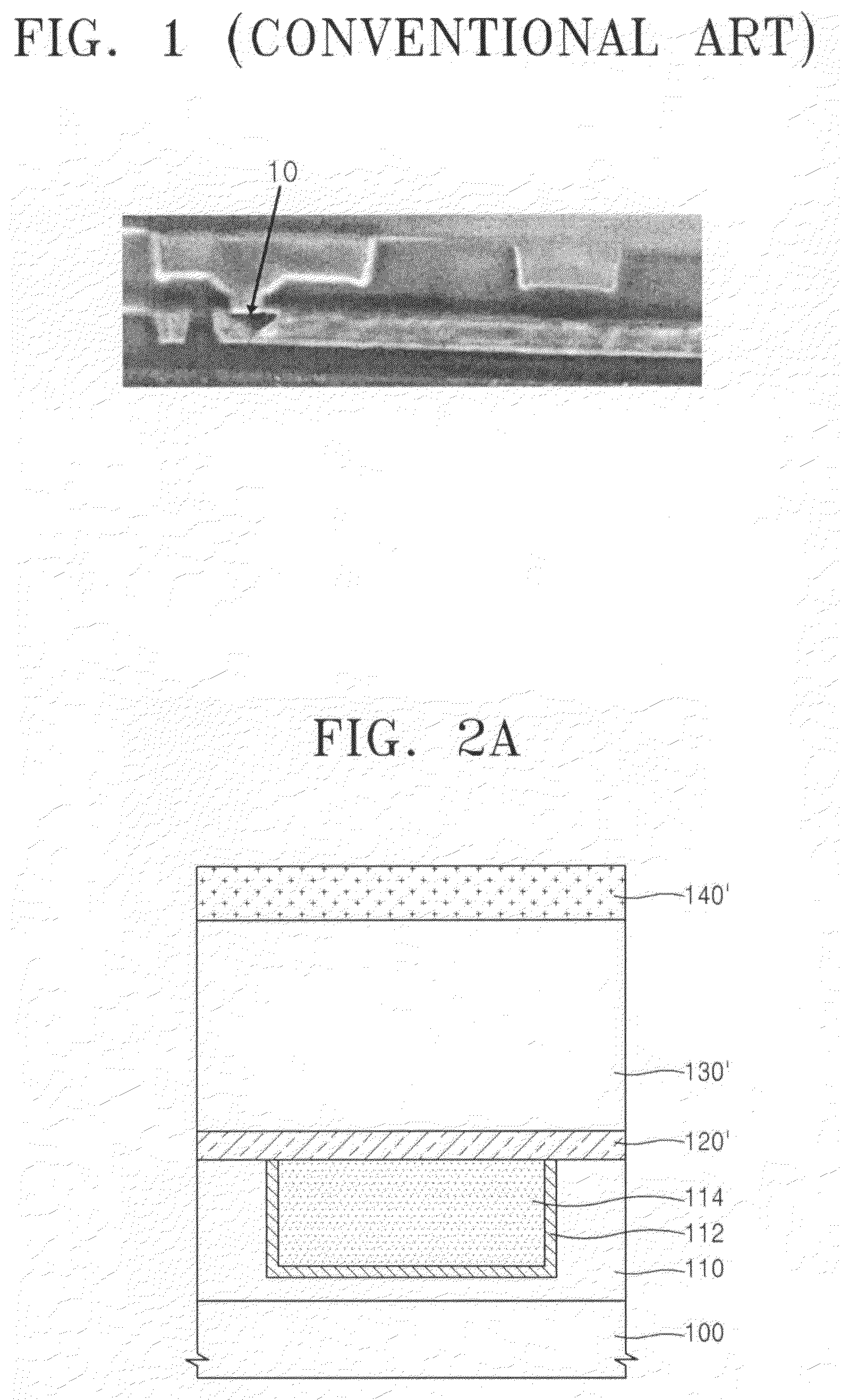
If the roughness of the surface of the metal wire is increased, electro-migration of the metal wire by electrical stress may be accelerated, which may result in the generation of voids in the contact of the metal wire in a short period of time near.
The void 10 may be generated due to the electro-migration of the metal wire, and may reduce the reliability of the wire.

Method used


Image

  • Semiconductor device and method of forming wires of semiconductor device
  • Semiconductor device and method of forming wires of semiconductor device
  • Semiconductor device and method of forming wires of semiconductor device

Examples


Embodiment Construction

[0029]Example embodiments will now be described more fully with reference to the accompanying drawings. Example embodiments may, however, be embodied in many different forms and should not be construed as being limited to the example embodiments set forth herein. Rather, these example embodiments are provided so that this disclosure will be thorough, and will fully convey the scope to those skilled in the art. Accordingly, well known processes, well known device structures, and well known techniques are not specifically described to avoid a vague interpretation of the example embodiments. Like reference numerals refer to like elements through the drawings.

[0030]It will be understood that when an element or layer is referred to as being “on”, “connected to” or “coupled to” another element or layer, it may be directly on, connected or coupled to the other element or layer or intervening elements or layers may be present. In contrast, when an element is referred to as being “directly o...


PUM

PropertyMeasurementUnit
temperatureaaaaaaaaaa

Abstract

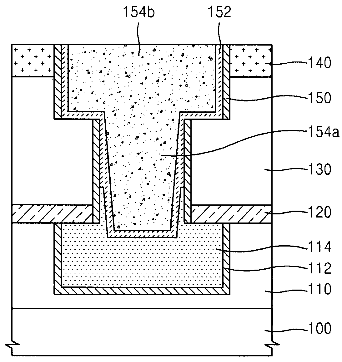
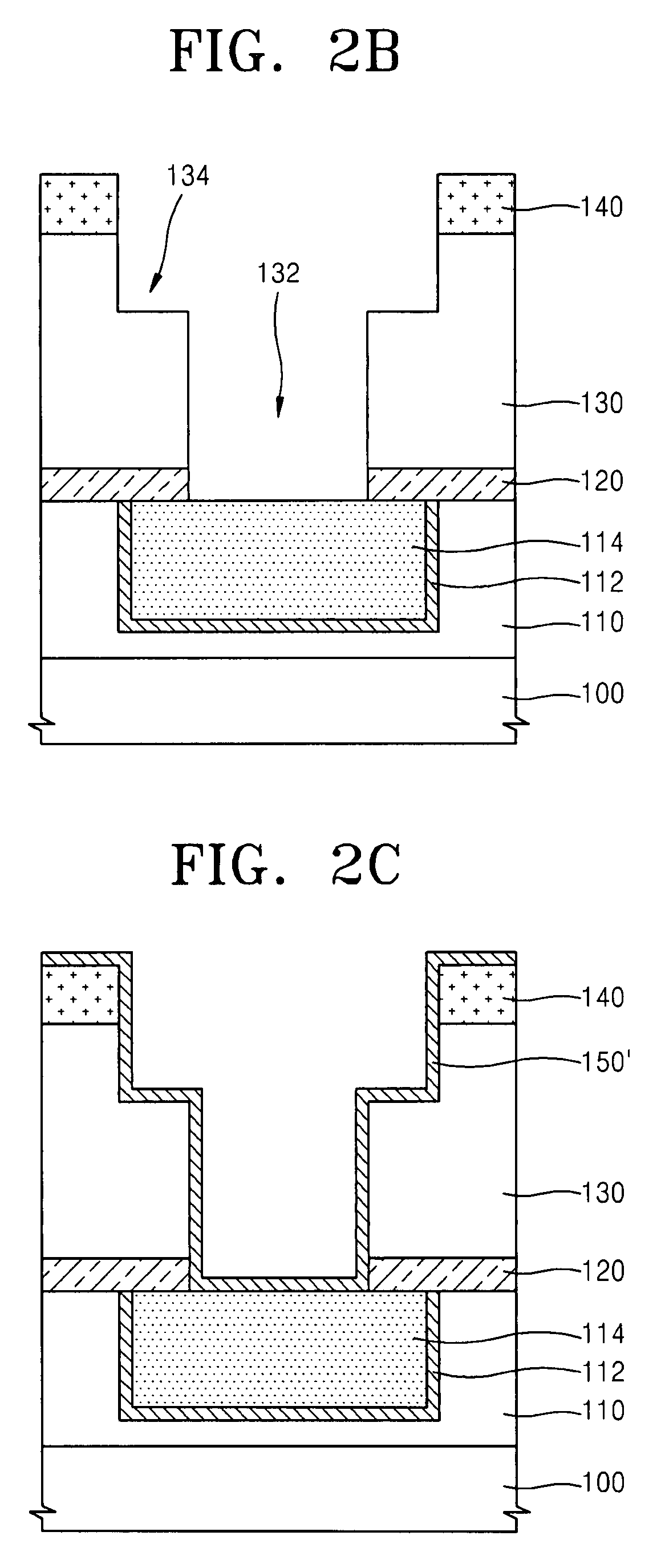
A method of forming wires of a semiconductor device including forming a first metal wire on a semiconductor substrate; forming a first insulating film on the first metal wire; etching a portion of the first insulating film to expose a surface portion of the first metal wire; forming a first barrier metal film on sidewalls of the opening and the exposed first metal wire; etching a portion of the first barrier metal film on the first metal wire to expose a surface portion of the first metal wire; performing a heat treatment process on the exposed surface portion of the first metal wire to improve surface roughness; and forming a second wire by filling the opening using a conductive material.

Description

PRIORITY STATEMENT[0001]This U.S. non-provisional application claims the benefit of priority from Korean Patent Application No. 10-2006-0010637, filed on Feb. 3, 2006, in the Korean Intellectual Property Office (KIPO), the disclosure of which is incorporated herein in its entirety by reference.BACKGROUND[0002]1. Field[0003]Example embodiments relate to a method of forming wires of a semiconductor device, for example, a method of forming wires of a semiconductor device in which a heat treatment process may be applied to a damascene structure wire to increase the reliability of the wire.[0004]2. Description of the Related Art[0005]As semiconductor devices become more highly integrated and are required to operate at higher speeds, metal wire structures having a lower resistance may be needed. For example, as the integration density of semiconductor devices increases, the structure of the metal wire may become more complicated.[0006]Thus, a multiple metal wire structure may be used in w...

Claims


Application Information

Patent Timeline
Patent Type & Authority Patents(United States)
IPC IPC(8): H01L21/4763
CPCH01L21/76805H01L21/76814H01L21/76844H01L21/76864H01L23/5226H01L23/53238H01L23/53295H01L21/76807H01L2924/0002H01L2924/00H02K3/04H02K41/025B60L13/03H02K11/40H02K2203/06
Inventor LEE, JUNG-EUNWEE, YOUNG-JINKIM, ANDREW-TAEMOON, YOUNG-JOON
Owner SAMSUNG ELECTRONICS CO LTD
Learn More