
Silicon wafer surface defect evaluation method

a technology of silicon wafers and defects, applied in the direction of semiconductor/solid-state device testing/measurement, instruments, under protective fluids, etc., can solve the problems of increased leak current of devices, poor evaluation throughput, high cost, etc., and achieve the effect of detecting quickly a region

Active Publication Date: 2009-12-15
SUMCO CORP
View PDF29 Cites 8 Cited by
  • Summary
  • Abstract
  • Description
  • Claims
  • Application Information

AI Technical Summary

Benefits of technology

The present invention provides a method for evaluating silicon wafers for defects using a rapid heat treatment and a surface photo voltage method (SPV method). This method can detect regions where small crystal defects exist, allowing for the manufacture of defect-free wafers. The method involves heating the wafer surface with a nitride film and calculating the minority carrier diffusion length on the surface using the SPV method. By detecting these defects, the method can facilitate the manufacture of high-quality silicon wafers.

Problems solved by technology

Further, when the COP exists on a wafer surface, steps may be generated in a device wiring process, resulting in disconnection.
Furthermore, the COP can be a factor of leak or the like in an element isolation portion to lower a yield of a product.
This OISF causes a defect, e.g., an increase in a leak current of a device.
However, the evaluation method using the copper decoration method disclosed in Patent Reference 1 or Patent Reference 2 can detect a COP whose size is less than a detection lower limit of a particle counter, but it is complicated since many steps are required for measurement, and hence there has been a problem that an evaluation throughput is poor and a cost is high.

Method used


Image

  • Silicon wafer surface defect evaluation method
  • Silicon wafer surface defect evaluation method
  • Silicon wafer surface defect evaluation method

Examples


example 1

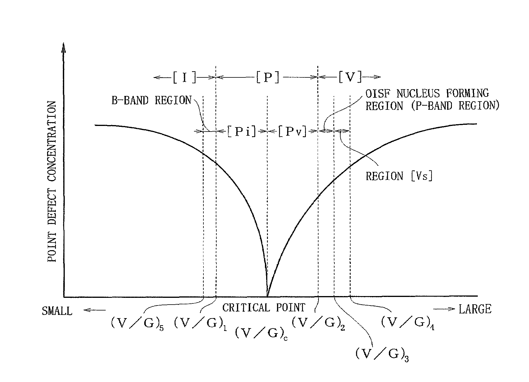
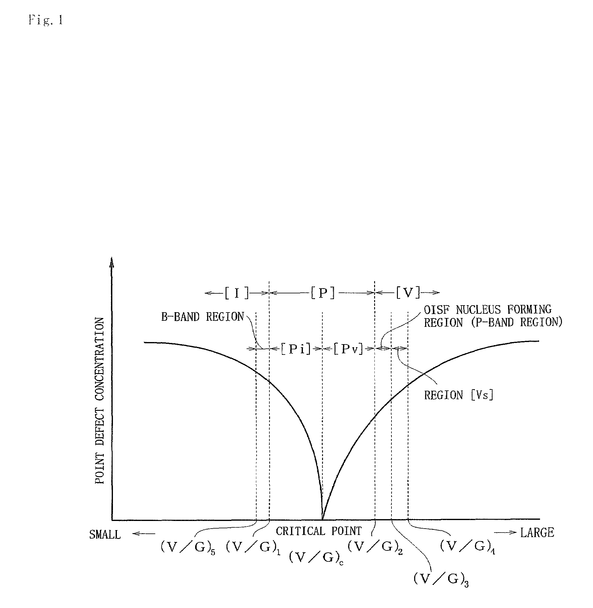
[0057]First, as shown in FIG. 1, a p-type silicon single-crystal ingot was pulled up, the ingot having a V / G ratio including a range of (V / G)1 to a critical point (V / G)c and a range of the critical point (V / G)c to (V / G)2, being controlled in such a manner that the V / C ratio consists of these ranges alone, and having a body portion with a diameter of 300 mm. This ingot was subjected to block cutting, external diameter grinding and orientation notch machining, and then it was sliced with a predetermined thickness, thereby a p-type silicon wafer having a diameter of 300 mm being cut out. A surface of this wafer was machine-polished to increase the parallelism, and thus an evaluation target wafer was provided.

[0058]Then, as a rapid heat treatment step, the wafer was put into a heat treatment furnace having an atmosphere which can nitride silicon by introducing a mixed gas containing an NH3 gas and an Ar gas at a ratio of 20:80, a heat treatment was performed at a temperature elevating s...

example 2

[0059]Surface defects on a wafer surface were detected like Example 1 except that a wafer cut out from a lot different from that of the wafer used in Example 1 was utilized as a measurement sample. That is, the wafer as an evaluation target in Example 2 is a wafer cut out from an ingot pulled up in a lot different from that of the ingot pulled up in Example 1. As shown in FIG. 1, like the ingot pulled up in Example 1, the ingot is a p-type silicon single-crystal ingot having a body portion with a diameter of 300 mm controlled in such a manner that a V / G ratio includes a range of (V / G)1 to a critical point (V / G)c and a range of the critical point (V / G)c to (V / G)2 and is composed of these ranges alone as pull-up conditions.

example 3

[0060]Surface defects on a wafer surface were detected like Example 1 except that a wafer cut out from a lot different from that of the wafers used in Examples 1 and 2 was utilized as a measurement sample. That is, the wafer as an evaluation target in this Example 3 is a wafer cut out from an ingot pulled up in a lot different from that of the ingots pulled up in Examples 1 and 2. Like the ingots pulled up in Examples 1 and 2, as shown in FIG. 1, the ingot is a p-type silicon single-crystal ingot having a body portion with a diameter of 300 mm controlled in such a manner that a V / G ratio includes a range of (V / G)1 to a critical point (V / G)c and a range of the critical point (V / G)c to (V / G)2 and is composed of these ranges alone as pull-up conditions of the ingot


PUM

PropertyMeasurementUnit
melting pointaaaaaaaaaa
diffusion lengthaaaaaaaaaa
temperatureaaaaaaaaaa

Abstract

There is provided a silicon wafer surface defect evaluation method capable of readily detecting a region where small crystal defects exist, the evaluation method comprising: a rapid heat treatment step of a silicon wafer from a silicon single-crystal ingot in an atmosphere which can nitride silicon at a temperature elevating speed of 10 to 150° C. / second from a room temperature to temperatures between not lower than 1170° C. and less than a silicon melting point, holding the silicon wafer at the processing temperature for 1 to 120 seconds and then cooling the silicon wafer to the room temperature at a temperature lowering speed of 10 to 100° C. / second; and a step of using a surface photo voltage method to calculate a minority carrier diffusion length on the wafer surface, thereby detecting a region on the wafer surface in which small COP's which cannot be detected at least by a particle counter exist.

Description

BACKGROUND OF THE INVENTION[0001]1. Field of the Invention[0002]The present invention relates to a method of evaluating a surface defect of a silicon wafer cut out from a silicon single-crystal ingot (which will be referred to as an ingot hereinafter). More particularly, the present invention relates to a silicon wafer surface defect evaluation method which facilitates manufacture of a defect-free region silicon wafer cut out from an ingot grown by a Czochralski method (which will be referred to as a CZ method hereinafter).[0003]2. Description of the Related Art[0004]With recent ultra-miniaturization of a semiconductor integrated circuit, as a factor which lowers a yield of a device, there is a crystal originated particle (which will be referred to as a COP hereinafter) which is a defect introduced in crystal growth, i.e., a defect formed in crystal growth of a silicon single-crystal ingot, a small defect of an oxygen precipitate which becomes a nucleus of an oxidation induced stack...

Claims


Application Information

Patent Timeline
Patent Type & Authority Patents(United States)
IPC IPC(8): C30B33/00
CPCH01L22/12H01L22/00
Inventor ITOU, WATARUHASEGAWA, TAKESHISHIOTA, TAKAAKI
Owner SUMCO CORP
Learn More