Method for improving operational efficiency in clogged induction melting and pouring furnaces

a technology of induction melting furnace and operational efficiency, which is applied in the field of methods, can solve the problems of affecting the melting electrical efficiency, the inductor's electrical efficiency is affected immediately, and the furnace is useless, and achieves the effect of rapid softening and removal

Active Publication Date: 2009-11-17
NARO RODNEY L
View PDF26 Cites 1 Cited by
  • Summary
  • Abstract
  • Description
  • Claims
  • Application Information

AI Technical Summary

Benefits of technology

[0024]Another aspect of the invention is to provide a flux addition to be utilized in the above-mentioned

Problems solved by technology

Eventually the clogging or restriction of furnace capacity will render the furnace useless and will affect the melting electrical efficiency.
When the induction channel experiences a clog or restriction in the molten metal flow, the electrical efficiency of the inductor is affected immediately and lost production from the inability to melt metal will result.
When this happens, insufficient metal flow through the inductor loop hampers heat transfer and interferes with the melting operation.
However, if slag build up occurs, the useful life may be reduced to only a few months or in some extreme cases, a few weeks.
It is very difficult to remove accumulations of slag from the inductor loop or throat area.
Because of the design of the furnace, access to the inductor loop is limited because it is covered by molten metal.
Draining the furnace may allow visual access to the inductor throat and loop area, but mechanically scraping the slag buildup, which is normally quite hard and tenaciously adheres to the loop wall, is extremely difficult.
These furnaces are not designed to melt metal.
This build-up must constantly be removed and a significant amount of labor is usually expended in keeping melting and pouring furnaces clean.
Ins

Method used


Image

  • Method for improving operational efficiency in clogged induction melting and pouring furnaces
  • Method for improving operational efficiency in clogged induction melting and pouring furnaces

Examples


Embodiment Construction

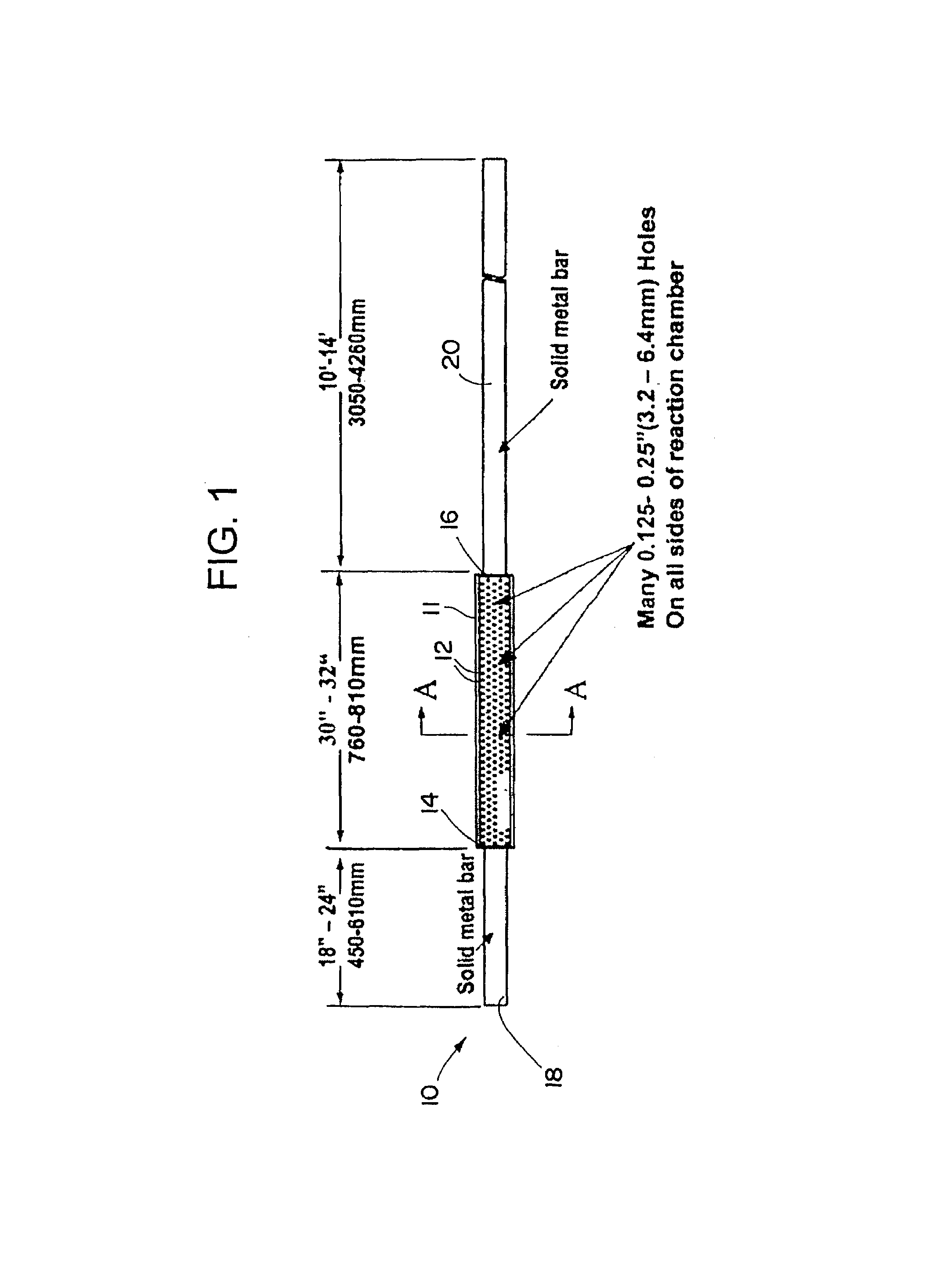
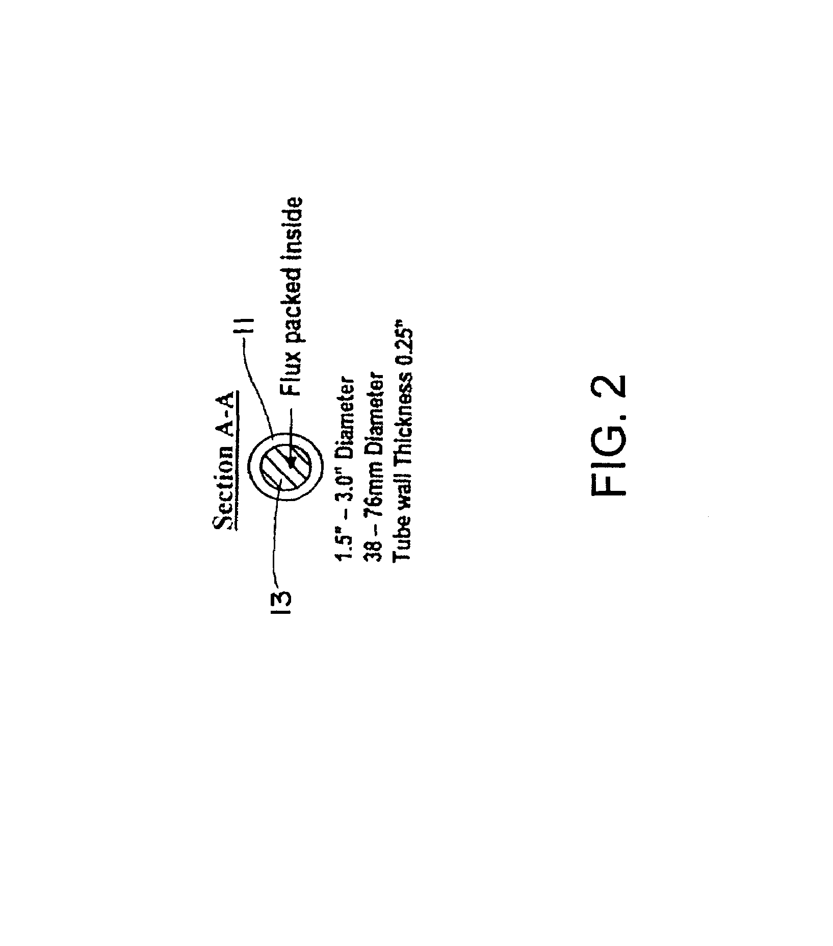
[0029]A fabricated plunging assembly is used for immersion into channel or pressure pour furnaces used to melt gray and ductile irons, copper-base alloys, aluminum-based alloys and zinc-based alloys. The plunging assembly is fabricated from a steel tube into which holes are drilled. The actual diameter of the holes is not critical but the holes must be small enough to contain the briquetted flux tablets. The length of the steel bars is such that the shorter bar acts as a channel loop locator when the plunging assembly is inserted under the molten metal bath. The longer of the steel bars is used as a handle for plunging the entire assembly under the molten bath and must be long enough to allow insertion of the tube into the body of the channel loop.

[0030]The dimensions depicted in Drawings 1 and 2 are representative of plunging assemblies that have successfully been used to unclog restricted inductor loops and restore the furnace back to its original efficiency. The apparatus 10 is c...


PUM

PropertyMeasurementUnit
Lengthaaaaaaaaaa
Lengthaaaaaaaaaa
Fractionaaaaaaaaaa

Abstract

A method of restoring the electrical efficiency of channel and pressure pour furnaces includes plunging a fluxing material with a specially designed plunging lance. The plunging lance chamber containing the fluxing material is 24 to 32 inches in length, 3 inches in diameter and has a capacity to hold 5 to 7.5 pounds of flux briquettes. The plunging chamber has holes drilled along the length of the body. The fluxing material contains by weight from 8.0 to 28.7% CaCO3 (calcium carbonate or limestone), from 0 to 18.5% MgCO3 (magnesium carbonate), from 3.6 to 18.0% Al2O3 (alumina) from 1.4 to 7.1% SiO2 (silica), in the form of a complex aluminosilicate, and from 19.4 to 46.4% Na2O (sodium oxide), in the form of soda ash (sodium carbonate). The total level of sodium ranges from 23 to 26% and up to 10% sodium fluoride or sodium chloride may be substituted for soda ash.

Description

[0001]This application is a continuation in part of U.S. patent application Ser. No. 10 / 695,248, filed Oct. 27, 2003 now abandoned, which is hereby incorporated by reference in its entirety.BACKGROUND OF THE INVENTION[0002]1. Technical Field of the Invention[0003]The invention relates specifically to a flux-filled plunging lance and procedures to repair and restore the operating efficiency and capacity of slag-clogged channel and pressure-pour furnaces used for melting and pouring gray, ductile and compacted graphite irons. The invention can be used for non-ferrous melting and pouring applications. The proprietary additives are included as part of the invention as well as the design of the plunging assembly.[0004]2. Description of the Related Art[0005]Induction furnaces are refractory lined vessels that utilize electrical current flowing through copper coils to create an electromagnetic or induction field on the inside and outside of the coil. When electrical current from the coils ...

Claims


Application Information

Patent Timeline
IPC IPC(8): B08B9/027B08B9/053
CPCB23K35/3602B23K35/3605B23K35/3607B23K35/361C21C1/08F27D25/001C22B9/003F27B14/065C21C7/076C21C2007/0062C22B9/103Y02P10/20Y02P10/25
Inventor NARO, RODNEY L.WILLIAMS, DAVID C.
Owner NARO RODNEY L
Why Eureka
Try Eureka